Functions
19
SMART Digital S
3
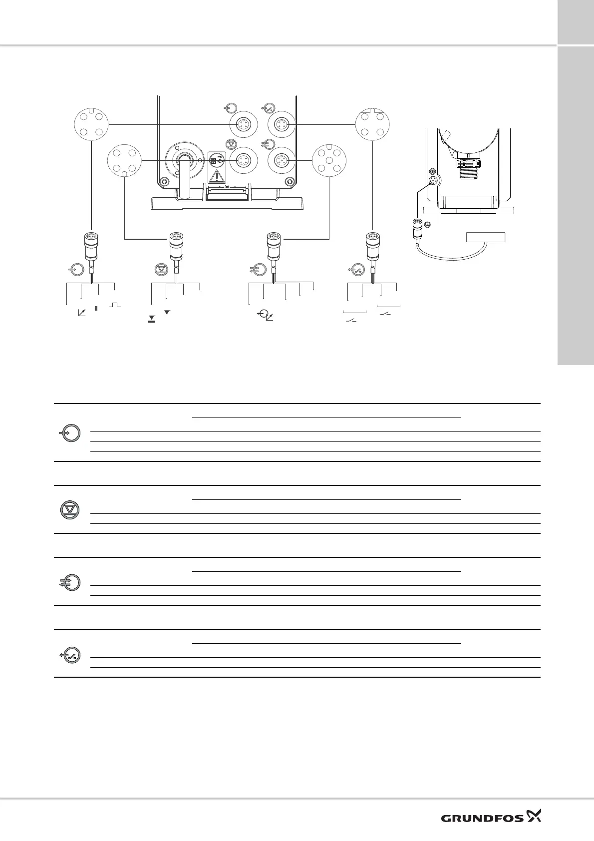
Wiring diagram, DDA
Cable 1: Analog, external stop and pulse input
Cable 2: Level input
Cable 3: GENIbus, analog output
Cable 4: Relay output
TM04 1121 0110 - TM06 8987 1517
2
1
3
4
2
1
3
4
5
2
3
4
1
2
1
3
►
2
1
GND
GND
BUS
BUS
GND
12
34
12
34
12
5
34
34
12
Cable 1
Analog/external stop/pulse
Product No.
2 m cable: 96609014
5 m cable: 96609016
Cable 2
Level input
see page 39, suction
lances
Cable 3
GENIbus, analog output
Product No.
2 m cable: 96632921
5 m cable: 96632922
Cable 4
Relay output
Product No.
2 m cable: 96609017
5 m cable: 96609019
FlowControl input
Sensor
Function
Pin holes
Plug type
1/brown 2/white 3/blue 4/black
Analog GND/ (-) mA (+) mA mA signal
External stop GND X Contact
Pulse GND X Contact
Function
Pin holes
Plug type
1234
Low level X GND Contact
Empty tank X GND Contact
Function
Pin holes
Plug type
1/brown 2/white 3/blue 4/black 5/yellow-green
GENIbus +30 V GENI bus A GENI bus B GND Bus
Analog output (+) mA GND/ (-) mA mA signal
Function
Pin holes
Plug type
1/brown 2/white 3/blue 4/black
Relay 1 X X Contact
Relay 2 X X Contact

 Loading...