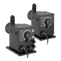
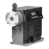
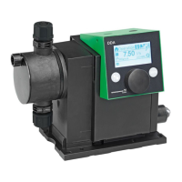
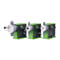
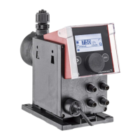
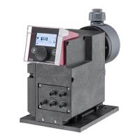
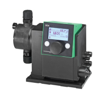
Pump selection
31
SMART Digital S
7
DDA, DDC, DDE, non-standard range
Key to the three following tables:
Maximum flow - pressure [l/h] - [bar]
Control variant
B: Basic (DDE)
P: B with pulse mode (DDE)
PR: P with relay output (DDE)
A: Standard (DDC)
AR: A with alarm relay and analog input (DDA, DDC)
FC: AR with FlowControl (DDA)
FCM: FC with flow measurement (DDA)
Materials
Dosing head
PP: PP
PVC: PVC (PVC dosing heads only up to 10 bar)
PV: PVDF
SS: Stainless steel 1.4401
Gaskets
E: EPDM
V: FKM
T: PT F E
Valve balls
C: Ceramic
SS: Stainless steel 1.4401
Control cube position
F: Front-mounted (change to left and right possible)
X: No control cube (DDE)
Supply voltage 3: 1 x 100-240 V, 50/60 Hz
Valve type
1: Standard
2: Spring-loaded (HV version)
Connection / Installation set
Suction / discharge connection
U2U2: Union nut G 5/8" with parts for hose connection 4/6 mm, 6/9 mm, 6/12 mm, 9/12 mm
U7U7: Union nut G 5/8" with parts for hose connection 0.17" x 1/4"; 1/4" x 3/8"; 3/8" x 1/2"
AA: Union nut G 5/8" with threaded connection Rp 1/4", internal thread
VV: Union nut G 5/8" with threaded connection 1/4" NPT, internal thread
XX: No connections included
Installation set*
I001: 4/6 mm (up to 7.5 l/h, 13 bar)
I002: 9/12 mm (up to 60 l/h, 9 bar)
I003: 0.17" x 1/4" (up to 7.5 l/h, 13 bar)
I004: 3/8" x 1/2" (up to 60 l/h, 10 bar)
Mains plug
F: EU
B: USA, Canada
G: UK
I: Australia, New Zealand
E: Switzerland
J: Japan
L: Argentina
Design
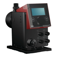
G: Grundfos red
A: Grundfos green
B: Grundfos black
X: Neutral/black
C: China approval
Special variant C3: Inspection Certificate 3.1 (EN 10204)
* Installation set includes 2 pump connections, foot valve, injection unit, 6 m PE discharge hose, 2 m PVC suction hose, 2 m PVC deaeration hose
(4/6 mm)
 Loading...
