Functions
15
SMART Digital S
3
Analog output
Applies to DDA
In addition to the analog input (operation mode: analog
0/4-20 mA) the pump is also equipped with an analog
0/4-20 mA output signal. Depending on the process
control requirements, the following analog output
settings are available:
* Output signal is calculated based on motor speed and pump status
(target flow rate).
Bus communication
Applies to DDA
The pump is equipped with a built-in module for
GENIbus communication. With the additional E-Box
module (please see page 36) the pump can be
integrated into a fieldbus network.
The bus communication possibilities enable remote
monitoring and setting via the fieldbus system.
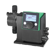
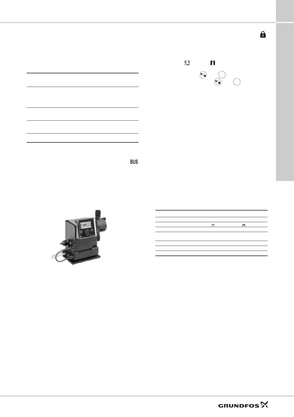
Fig. 15 DDA with E-box
Key lock and mechanical lock
Applies to DDA, DDC
To protect the pump from maloperation, a key lock can
be set by entering a 4-digit PIN-code. When the pump
is locked, it is still possible to navigate through the
menus Alarm and Info and to acknowledge
alarms. Two levels of protection are available:
• Settings: the keys and are still available.
• Settings + keys: the keys and are also
locked.
For temporary (2 minutes) or final deactivation the
preset 4-digit pin-code has to be entered again.
Applies to DDE
The adjustment knob can be locked with a locking
screw to fix the current setting.
Basic settings
Applies to DDA, DDC
With load factory settings, the pump can be reset to
the default settings. In addition, with save customer
settings, the current configuration of the pump is
stored and can be activated later by load customer
settings. The latest saved configuration is stored in the
memory.
Units
Applies to DDA, DDC
It is possible to select metric units (litre/millilitre/bar) or
US units (US gallons/psi). Depending on the operation
mode and menu, the following units are displayed:
Setting
Description of analog
output signal
Control variant
FCM FC AR
Output = Input
Analog feedback signal (not
for master-slave application).
The analog input signal is
mapped 1:1 to the analog
output.
XXX
Actual flow
Flow measured in the dosing
head
(Flow Measurement page 18)
XX*X*
Backpressure
Backpressure measured in
the dosing head
(Pressure monitoring page 18)
XX
Bus control
Set by a command in the bus
communication (see below)
XXX
TM04 1640 2617
Operation mode/Function Metric units US units
Manual control ml/h or l/h gph
Pulse control ml/ ml/
Analog 0/4-20 mA control ml/h or l/h gph
Batch control
(pulse- or timer-based)
ml or l gal
Calibration ml ml
Volume counter l gal
Pressure monitoring bar psi
 Loading...