13
English (US)
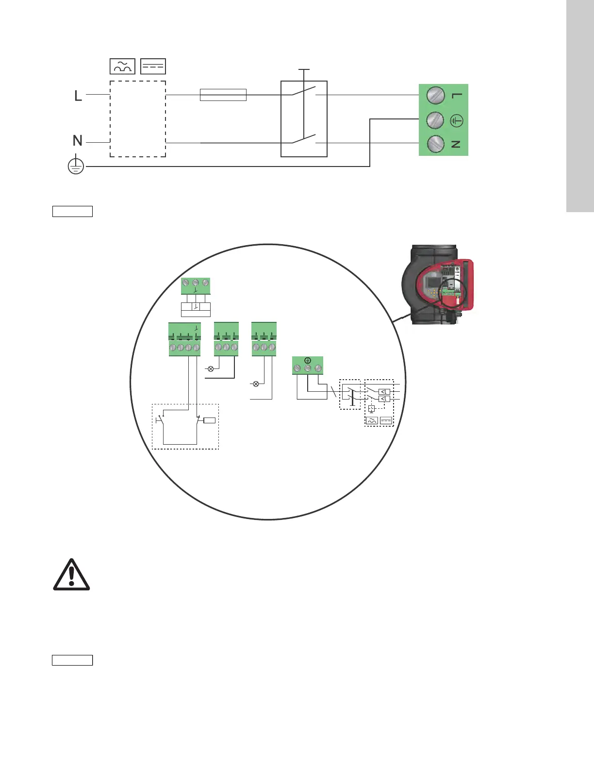
5.4 Connection diagram
Fig. 14 Example of typical connection, 1 x 230 V ± 10 %, 50/60 Hz
5.4.1 Connection to external controllers
Fig. 15 Example of connections in the control box
Concerning demands on signal wires and signal transmitters, see
section 19. Technical data.
Use screened cables for external on/off switch, digital input,
sensor and setpoint signals.
TM03 2397 0312
External switch
Fuse
(min. 10 A, time lag)
GFCI
All cables used must be connected in accordance with local regulations.
TM05 2673 3812
NC NO C NC NO C
NL
S/S
M
I
M
A
signal
sensor
Vcc
24V
IN
Mains
connection
Alarm
Operation
Start/
stop
On/off timer
Analog input
Warning
Wires connected to supply terminals, outputs
NC, NO, C and start/stop input must be separated
from each other and from the supply by
reinforced insulation.
All cables used must be heat-resistant up to
+185 °F (+85 °C).
 Loading...