4 of 36© 2009 D 664 - 07/09
Sequence of Operation
Section A
General
Operation
Page 4 - 5
Section B
Snow
Melting
Page 5 - 7
Section C
Boiler
Operation
Page 7 - 9
Section D
Melting Enable
/ Disable
Page 9 - 11
Section E
Melting
Operation
Page 12 - 13
The following defined terms and symbols are used throughout this manual to bring attention to the presence of hazards of various risk
levels, or to important information concerning the life of the product.
- Warning Symbol: Indicates presence of hazards which can cause severe personal injury, death or
substantial property damage if ignored.
- Double insulated
- Local level, appliances
INSTALLATION
CATEGORY II
Definitions
Section F
Idling
Operation
Page 14
POWERING UP THE CONTROL
When the Snow Detector and Melting Control 664 is powered up, the control displays all LCD segments for 2 seconds, then the
control type number in the LCD for 2 seconds. Next, the software version is displayed for 2 seconds. Finally, the control enters into
the normal Operating mode and the LCD defaults to displaying the current outdoor air temperature.
MIXING DEVICE SELECTION (MIXING)
The 664 can supply a lower fluid temperature to the snow melting system by using a variable speed injection pump, a floating action
mixing valve or a modulating 4-20 mA device. The selection is made under the Mixing item in the ADJUST menu.
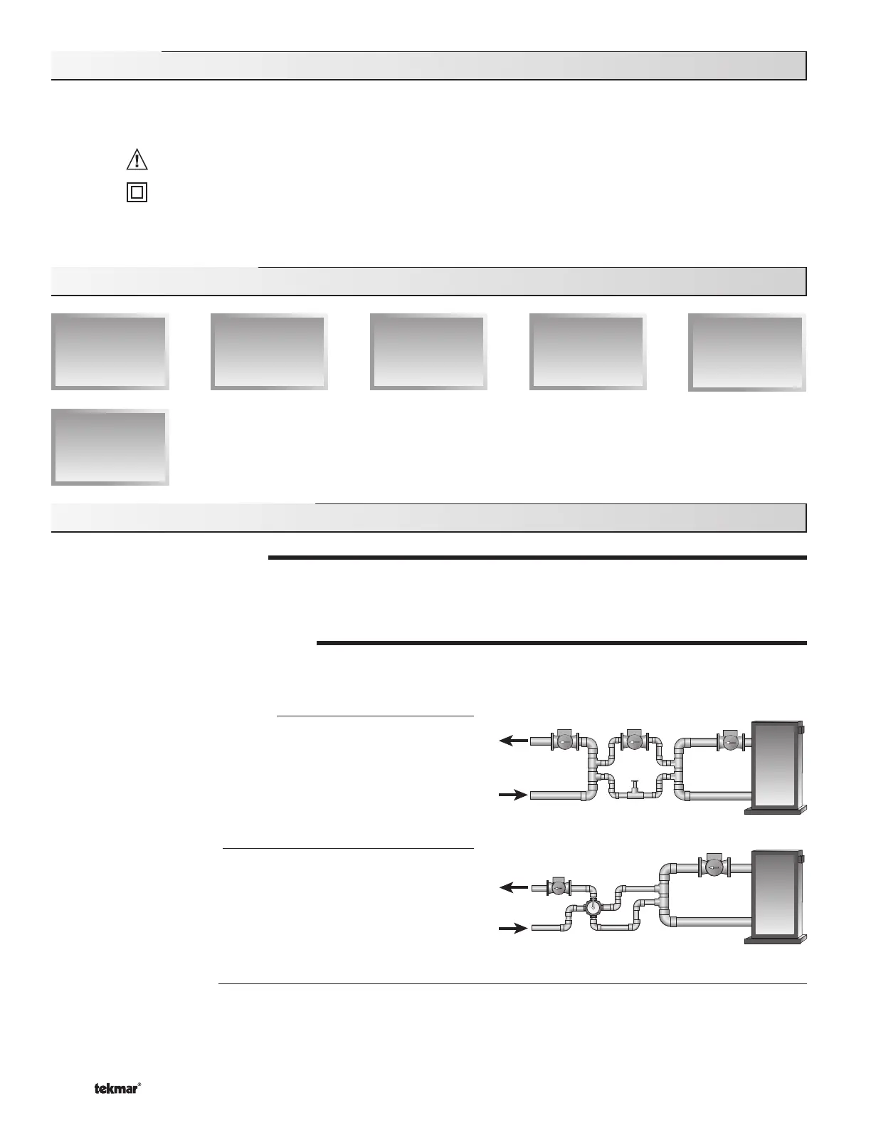
Variable Speed Injection (VAR)
A standard wet rotor circulator is connected to the 664 on the Pwr Mix
and Opn / Var terminals (4 and 3). The 664 increases or decreases the
power output to the circulator based on the system requirements. For
correct sizing and piping of the variable speed injection pump, refer to
Essay E 021. A visual indication of the current variable speed output is
displayed in the LCD in the form of a segmented bar graph.
Floating Action (FLOT)
A floating action motor is connected to the 664 on the Pwr Mix,
Opn / Var and Cls terminals (4, 3 and 5). The 664 pulses the actuator
motor open or close based on the system requirements. The mixing
valve that the actuator is connected to can be either a 2-way, 3-way or
4-way valve. A visual indication of the current position of the valve is
displayed in the LCD in the form of a segmented bar graph.
4-20 mA Output (4-20)
A 4-20 mA device is connected to the 664 on the 4-20 mA + and 4-20 mA – terminals (1 and 2). The 664 increases or decreases
the modulating output to the 4-20 mA device based on the system requirements. The 4-20 mA output can be used to operate a
variety of actuating motors for mixing valves and motor drives for larger pumps. A visual indication of the current output of the
4-20 mA device is displayed in the LCD in the form of a segmented bar graph.
Section A: General Operation

 Loading...


