Description English
Plate Heat Exchanger 1
EN
EN
Description
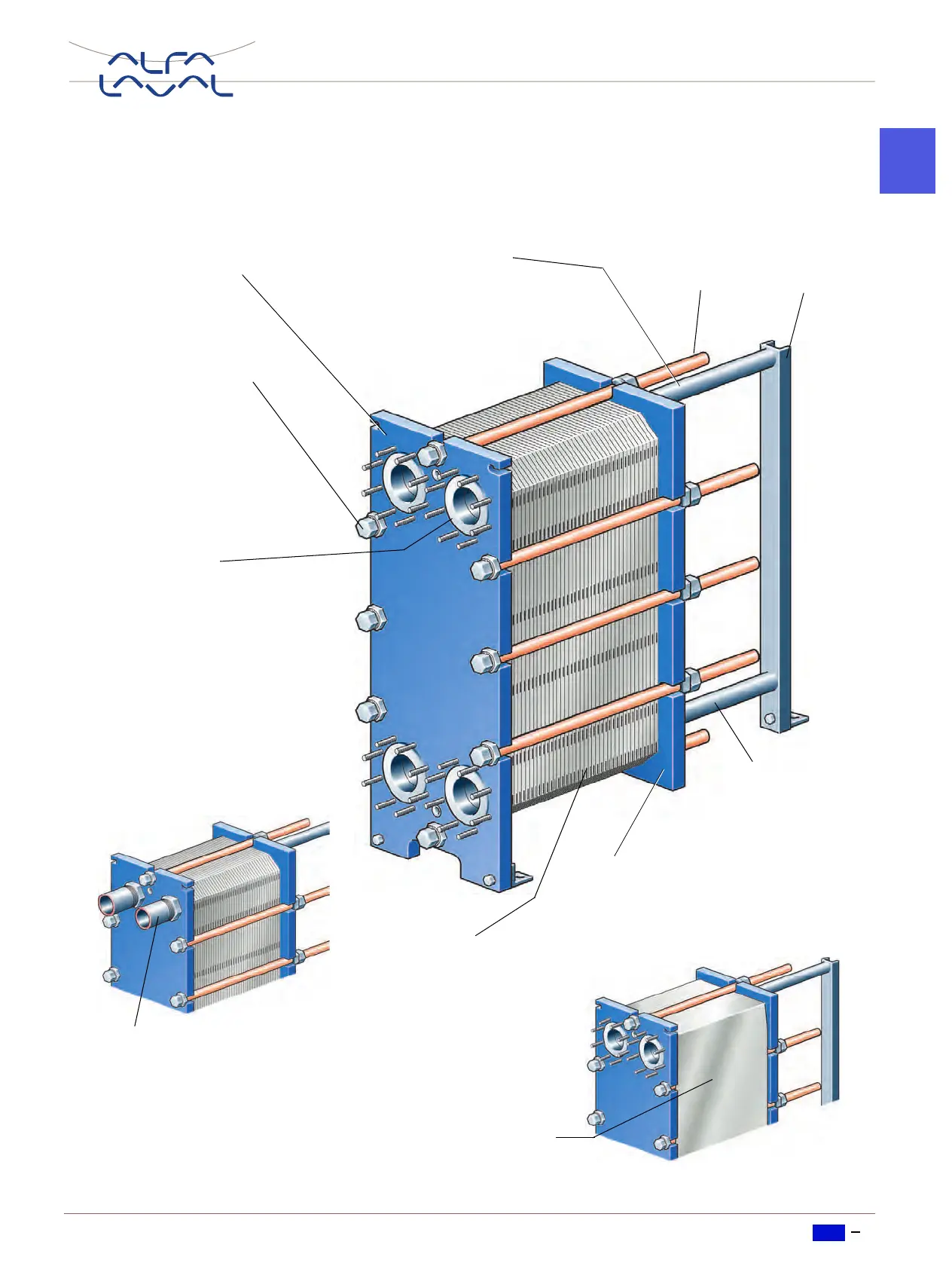
Main components
Support
column
Frame plate
Carrying bar
Carries the channel plates
and the pressure plate.
Connections
Holes through the frame plate,
permitting the media to enter into
the heat exchanger.
Threaded studs around the
holes secure the pipes to the ap-
paratus. Metallic or rubber-type
linings may be used to protect
the holes against corrosion.
Connections can also be pipes
for welding or threaded.
Tightening bolts
Press the channel
plates together.
Pressure plate
Moveable steel plate. In some cases
pipes may be connected to the pres-
sure plate.
Channel plates
Heat is transferred from one
medium to the other through
the thin channel plates.
The number of plates deter-
mines the total heat transfer
surface.
Guiding bar
Keeps the channel
plates in line at thei
lower end.
Bolt
protection
Pipe connections
Protective sheets
In the USA mandatory, in
other countries optional.

 Loading...


