12 of 36© 2009 D 664 - 07/09
Section E: Melting Operation
Section E1
General Melting
Operation
Section E1: General Melting Operation
The Snow Detector and Melting Control 664 provides up to two zones of snow melting. In order for the snow melting system to be
started, one of the methods described in Section D1 must be used. Once a melting enable signal is applied and the zone(s) is not in
WWSD or the system is not in CWCO, the Melting mode begins. When the control is in the Melting mode, the Melting pointer is visible
in the VIEW menu. The MELT 1 and the MELT 2 settings in the ADJUST menu sets the slab surface temperatures of zone 1 and zone
2 respectively. When the zone(s) is melting and its slab temperature is warming up to its slab target temperature, STRT is displayed in
the STATUS item of the appropriate zone while in the VIEW menu. The zone(s) fi nishes melting when its slab temperature has been
at least its slab target temperature for a period of time. This period of time is based on whether an automatic or manual melting enable
signal starts the snow melting system.
If an automatic melting enable signal starts the snow melting system, DET is displayed in the STATUS item of the appropriate zone
while in the VIEW menu once the slab temperature of the currently operating zone(s) reaches its slab target temperature. The currently
operating zone(s) continues to melt either until the 090 becomes dry, or any additional running time has expired. Once the Melting mode
is complete, the zone(s) operates in the Idling mode.
If a manual melting enable signal starts the snow melting system, the running time is displayed in the STATUS item of the appropriate
zone while in the VIEW menu and begins counting down once the slab temperature of the currently operating zone(s) reaches its slab
target temperature. The currently operating zone(s) continues to melt until the running time counts down to 0:00. Once the Melting mode
is complete, the zone(s) operates in the Idling mode. The table on page 14 describes how the control responds to enable and disable
signals.
ZONE 1 and 2 (ZONE)
The Zone 1 and 2 setting may be selected to AUTO or OFF. When AUTO is selected, the zone is activated and the control operates
the appropriate zone. When OFF is selected, the control does not operate the zone.
SLAB TEMPERATURE CONTROL
The 664 uses a sensor in zone 1 and zone 2 to provide slab temperature control. Zone 1 has the option to use either the Snow / Ice
Sensor 090 or the Slab Sensor. Zone 2 can only use the Slab Sensor.
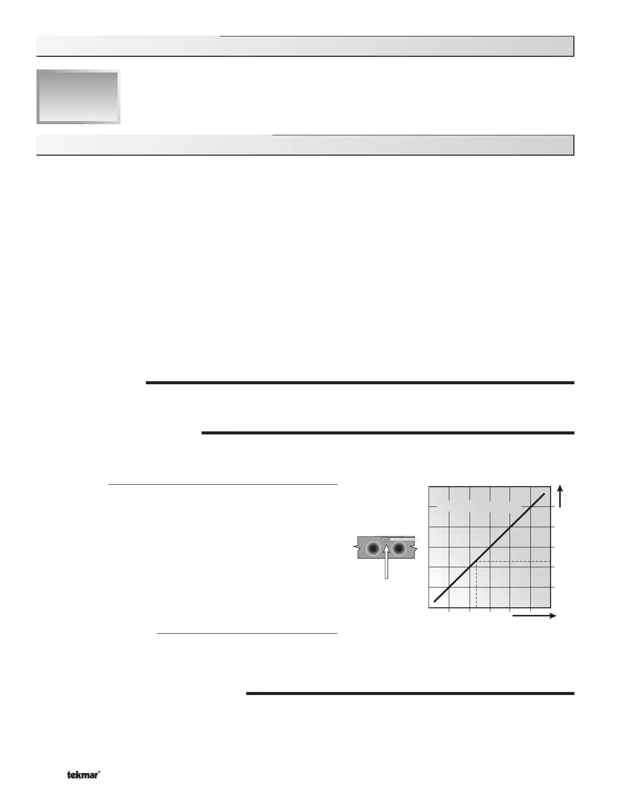
Slab Sensor
If a Slab Sensor is used, the control assumes that the sensor is
approximately 1 inch below the surface of the snow melting slab. Since
this point is closer to the source of the heat, this point is warmer than
the surface of the slab. Therefore, the sensor must be maintained at
a higher temperature in order to ensure that the surface of the slab
is maintained at the correct temperature. The amount of temperature
difference between the surface of the slab and the slab sensor changes
with the outdoor temperature. Therefore, the slab core temperature
is increased as the outdoor air temperature drops. The temperature
displayed as the slab temperature (SLAB 1 and / or SLAB 2) is the
temperature of the slab sensor.
Snow / Ice Sensor 090
The temperature displayed as the slab temperature (SLAB 1) is the
slab temperature of zone 1. This temperature is calculated from the
edge sensor and the center sensor built into the 090.
SLAB TARGET TEMPERATURE (SLB TRG)
The SLB1 TRG and the SLB2 TRG temperatures are determined from the Melting settings (MELT 1 and MELT 2 respectively),
or Idle settings (IDLE 1 and IDLE 2 respectively) and the outdoor air temperature. The control displays the temperature(s) that it is
currently trying to maintain at the slab sensors of zone 1 and zone 2. If the control does not presently have a requirement for heat, it
displays “– – –” in the STATUS item of the appropriate zone while in the VIEW menu.
Surface temperature = 35°F
Decreasing Air Temperature
Increasing Slab Core Temperature
Slab Surface Temperature is Constant
Slab Outdoor ResetSlab Outdoor Reset
Core (sensor)
is warmer

 Loading...


