© 2005 D 090 - 08/05
3 of 4
Installing Brick Pavers
If using brick pavers instead of concrete, it is recommended to mortar surrounding brick pavers to the side of the socket. This
ensures good thermal conduction from the brick pavers to the socket. The top of the brick pavers should be level with the socket
when the plastic plug is installed.
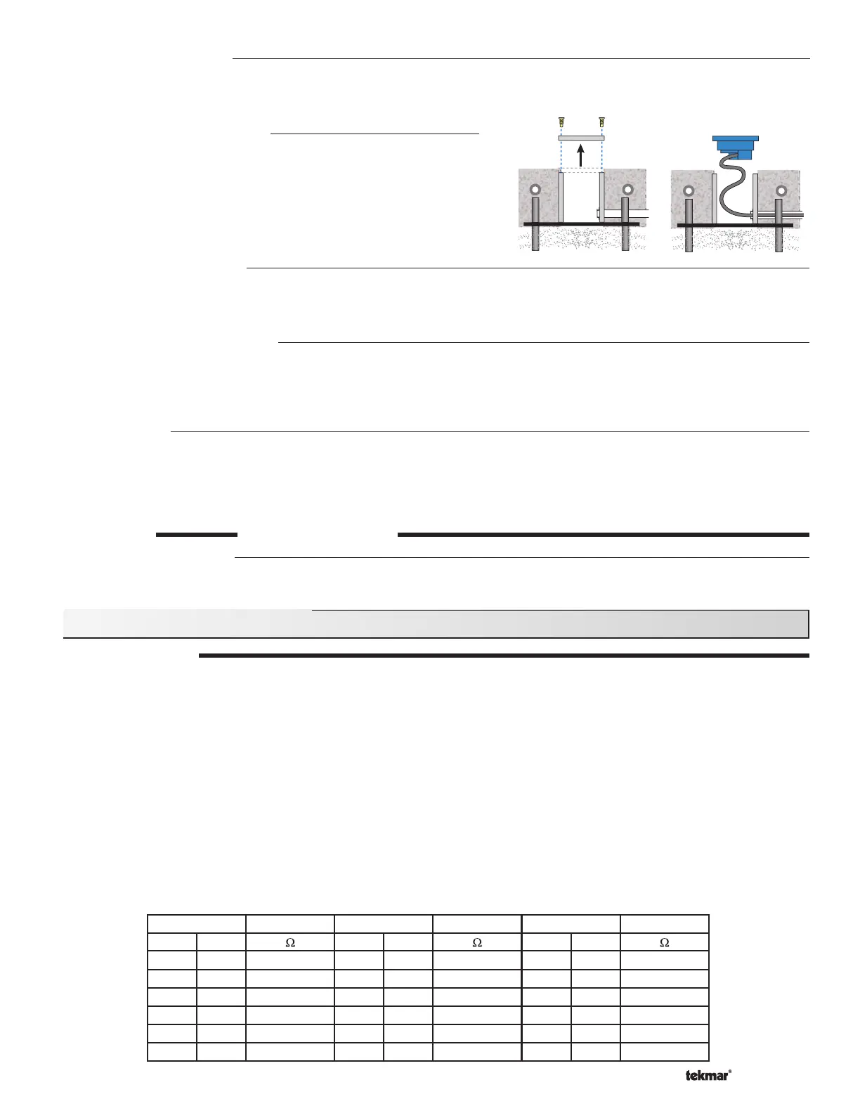
Install the Sensor and Cable
When the snow melt surface is finished, remove the plastic plug from
the socket and fish the cable through the conduit until there is only
6 to 12” (150 to 300 mm) of cable between the sensor and conduit.
Loop this remaining extra wire in a loose coil so as to not twist it,
and place it, and the sensor into the socket. Secure the sensor to the
socket with the four screws provided, making sure the “O” ring is in
place and properly seated.
TEST THE SENSOR
When performing these tests:
• The sensor head should be installed in the slab.
• The five cable wires at the control should be disconnected (unplug terminal plug).
• Use a good quality electrical testing meter with an ohm scale range of 0 to 2,000,000 Ohms.
The sensor has two 10k Ohm thermistors. One reads slab surface temperature, and the other checks sensor heater temperature.
If the sensor has been disconnected from the control for an hour or more, the readings for both thermistors should be very close.
• Using the ohmmeter and standard testing practices, measure the resistance between:
(a)
the yellow and black sensor wires (sensor temperature), and
(b)
the brown and black sensor wires (slab temperature).
The table below lists the expected resistance values at various sensor temperatures.
•
Measure the resistance between the blue and black wires. When the sensor surface is dry, the reading should be 2,000,000 Ohms.
When the sensor surface is wet it should be between 10,000 and 300,000 Ohms.
• Measure the resistance between the red and black wires of the heating element. This reading should be close to 50 Ohms.
Testing and Troubleshooting
Temperature Resistance
°F °C
-49 -45 472,000
-40 -40 337,000
-31 -35 243,000
-22 -30 177,000
-13 -25 130,000
-4 -20 97,000
Temperature Resistance
°F °C
5-15 72,900
14 -10 55,300
23 -5 42,300
32 0 32,600
41 5 25,400
50 10 19,900
Temperature Resistance
°F °C
59 15 15,700
68 20 12,500
77 25 10,000
86 30 8,060
95 35 6,530
104 40 5,330
Replacing old 090 or 094
Current versions of the Snow / Ice socket 091 use #6-32 screws. Previous versions of the 091 used smaller #4-40 screws. When
replacing an 090 or 094, both sets of screws are provided. It is recommended to try the smaller screws first to avoid cross
threading.
Salt and Brine Contamination
The performance of the snow / ice sensor water detection can be compromised when exposed to deicing agents such as road
salt, magnesium chloride, or calcium chloride. These contaminants can permanently damage the sensor. It is recommended to
locate the sensor away from areas exposed to these deicing agents when at all possible. Locations to avoid could include tire
track areas or areas close to a curb where traveling vehicles may splash contaminated water on to the sensor.
Maintenance
The Snow / Ice Sensor is installed in a hostile environment. Accumulation of dirt, salty grime, etc., on its surface will inhibit proper
water detection. It should be checked on a regular basis and, when necessary, cleaned. Before cleaning, the control power should
be shut off to prevent the control from entering the snow melt mode. Next, use a soft bristle brush and warm soapy water to clean
the sensor surface. Do not use a steel wire brush as this will damage the sensor. Then use a paper towel to thoroughly dry the
sensor surface. After cleaning, re-power the control and push the test button to cycle the control through the test routine.
STEP THREE
WIRING THE SENSOR
Electrical Connections
The snow / ice sensor cable has 5 wires: Red, Black, Blue, Yellow, and Brown. The wires connect to the respective Red, Black,
Blue, Yellow and Brown terminals on the Snow Detector & Melting Control.

 Loading...


