© 2005 D 090 - 08/05
2 of 4
Conduit
Place the sensor socket at the chosen location and run a conduit for the cable from the socket to the snow / ice detection control.
If more than 210’ (64 m) of cable is required to reach the control, run the conduit to a weatherproof junction box. The sensor cable
should be run in its own conduit and not in combination with high voltage wiring.
The conduit length from the sensor to the junction box should be less than the 210’ (64 m) of cable supplied with the 094 snow / ice
sensor.
At the junction box, additional 18 AWG, 5 conductor cable can be spliced on to increase the total length to 500’ (150 m) from the
sensor to control.
Avoid tying the conduit to the rebar within 6’ (2 m) of the socket. This allows the rebar grid to move without disturbing the position
of the socket.
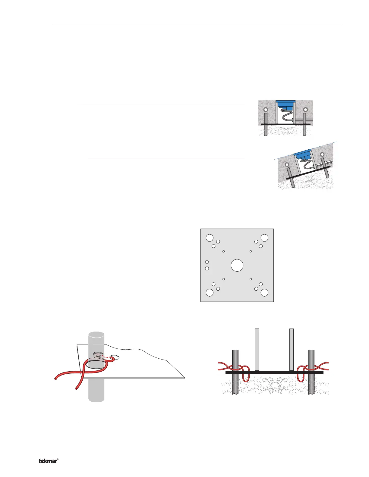
Sloped Surfaces
The top of the snow / ice sensor should be flush and parallel to that of the snow melt
surface.
When the sensor is installed on a sloped driveway, the sensor must be installed near
the lowest elevation of the slope. This is required since the melting snow or ice runoff
water will drain toward the lowest point on the driveway and keep this area wet for longer
periods of time.
Installing the Socket
A mounting plate has been included to simplify the installation of the sensor socket.
When possible, the mounting plate should be located directly on top of gravel in order
to provide good drainage. If the slab is more than 4” thick, a mound of crushed rock or a
styrofoam or wooden block can be used to elevate the socket. A hole must be punched
or drilled in the styrofoam or wooden block in order to provide drainage.
Mounting Plate
1.
Drainage hole
2. Socket screw holes
3. Rebar holes
4. Rebar tie holes
5. Conduit tie holes
3 3
3 3
4 4
4 4
5
2
1
2
2 2
Failure to provide adequate drainage under the socket may reduce the life expectancy of the snow / ice sensor.
The mounting plate can be fastened to the ground by driving 1/2” (12.7 mm) rebar through the four holes located on each of the
four corners and then tying the mounting plate to the rebar.
1) Cut four pieces of rebar at least 12” (300 mm) long.
2)
Drive the rebar into the ground through each of the mounting plate
rebar holes. Leave approximately 2” (50 mm) of rebar above the
ground.
3)
Cut several 12” (300 mm) pieces of steel wire.
4) Form a “U” shape and pull wire through the rebar tie hole from
the bottom to the top side.
5) Repeat by pulling the “U” shape from the top to the bottom side.
6) Repeat (4) and (5) for each of the four corners.
7) Cross the wire, then wrap around the rebar.
8) Twist wire using pliers to tighten.
The mounting plate also has conduit tie holes to allow a cable tie
or steel wire to fasten the conduit to the mounting plate.
Placing Concrete
A plastic plug is provided with the socket to prevent it from being accidentally filled with concrete. The plastic plug is the same
thickness as the sensor flange. This allows the finished surface of the concrete (asphalt, etc.) to be troweled flush with the plug.
The plug must be installed prior to placing the concrete. Also ensure that the mounting plate drainage hole remains unplugged
once the concrete has cured.

 Loading...


