English (US)
14
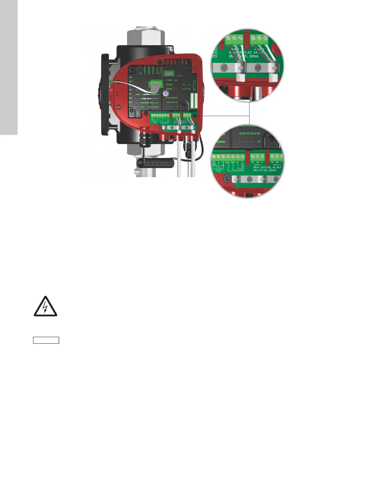
Fig. 16 Wiring diagram, 32-XX versions
The connection terminals of 32-XX versions differ from those of
terminal-connected versions, but they have the same function
and connection options.
Use screened cables for external on/off switch, digital input,
sensor and setpoint signals.
Connect screened cables to the ground connection as follows:
• Terminal-connected versions:
Connect the cable screen to ground via the digital-input
terminal (earth).
• Plug-connected versions:
Connect the cable screen to ground via cable clamp.
TM05 8539 2413
Warning
Wires connected to supply terminals, outputs
NC, NO, C and start/stop input must be separated
from each other and from the supply by
reinforced insulation.
All cables used must be heat-resistant up to
+85 °C.
All cables used must be installed in accordance
with EN 60204-1 and EN 50174-2:2000.

 Loading...


