English (GB)
15
Analog, external stop and pulse input
Level signals: empty and low-level signal
GENIbus, analog output
Relay outputs
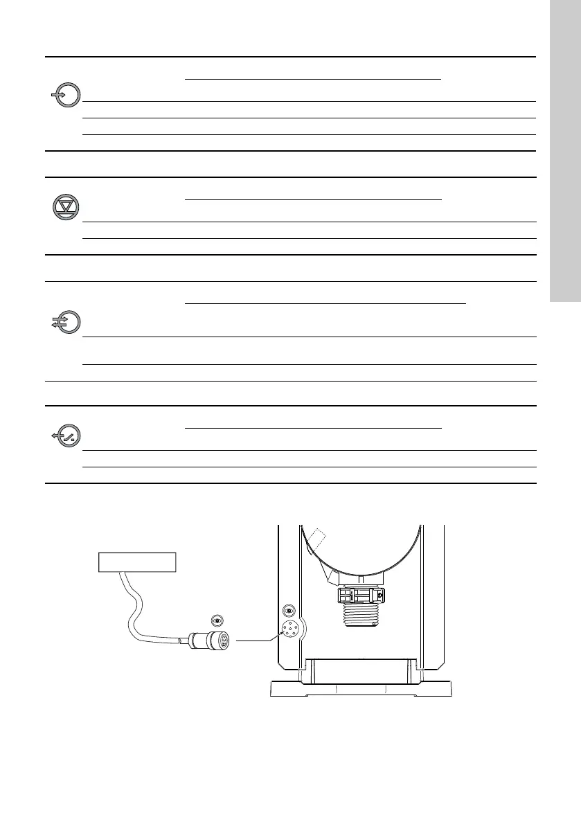
FlowControl signal connection
Fig. 11 FlowControl connection
Function
Pins
Plug type
1/brown 2/white 3/blue 4/black
Analog GND/ (-) mA (+) mA mA signal
External stop GND X Pulse
Pulse GND X Pulse
Function
Pins
Plug type
1/brown 2/white 3/blue 4/black
Low-level signal X GND Pulse
Empty signal X GND Pulse
Function
Pins
Plug type
1/brown 2/white 3/blue 4/black
5/yellow/
green
GENIbus +30 V
GENI bus
TXD
GENI bus
RXD
GND Bus
Analog output (+) mA GND/ (-) mA mA signal
Function
Pins
Plug type
1/brown 2/white 3/blue 4/black
Relay 1 X X Pulse
Relay 2 X X Pulse
TM04 1158 0110
 Loading...