English (GB)
13
4.2 Hydraulic connection
Important information on installation
• Observe suction lift and line diameter, see
section 3.1 Technical data.
• Shorten hoses at right angles.
• Ensure that there are no loops or kinks in the
hoses.
• Keep suction line as short as possible.
• Route suction line up towards the suction valve.
• Installing a filter in the suction line protects the
entire installation against dirt and reduces the
risk of leakage.
• Only control variant FC/FCM: For discharge
quantities < 1 l/h we recommend the use of an
additional spring-loaded valve (approx. 3 bar) on
the discharge side for the safe generation of the
necessary differential pressure.
Hose connection procedure
1. Push union nut and tensioning ring across hose.
2. Push cone part fully into hose, see fig. 8.
3. Attach cone part with hose to corresponding
pump valve.
4. Tighten union nut manually.
– do not use tools!
5. Tighten up union nuts after 2-5 operating hours if
using PTFE gaskets!
6. Attach deaeration hose to the corresponding
connection (see fig. 3) and run into a container
or a collecting tray.
Fig. 8 Hydraulic connection
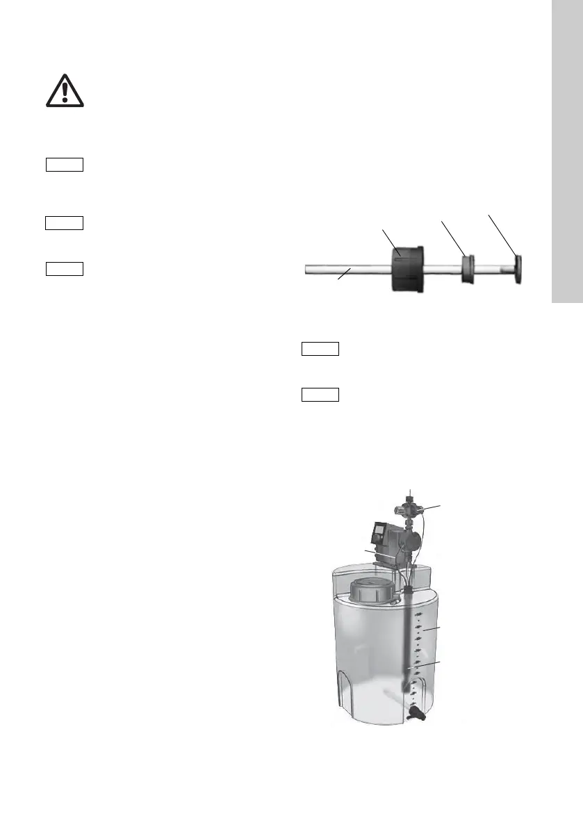
Installation example
The pump offers various installation options. In the
picture below, the pump is installed in conjunction
with a suction line, level switch and multifunction
valve on a Grundfos tank.
Fig. 9 Installation example
Warning
Risk of chemical burns!
Wear protective clothing (gloves and
goggles) when working on the dosing
head, connections or lines!
The dosing head may contain water
from the factory check!
When dosing media which should not
come into contact with water, another
medium must be dosed beforehand!
Faultless function can only be
guaranteed in conjunction with lines
supplied by Grundfos!
The lines used must comply with the
pressure limits as per section
3.1 Technical data!
TM04 1155 0110
Pressure differential between suction
and discharge side must be at least
1 bar / 14.5 psi!
Tighten up the dosing head screws
once before commissioning and after
2-5 operating hours at 3 Nm.
TM04 1183 0110
Union nut
Tensioning ring
Cone part
Hose
Deaeration
hose
Tank
Multifunction
valve
Suction line
with empty
signal