English (GB)
34
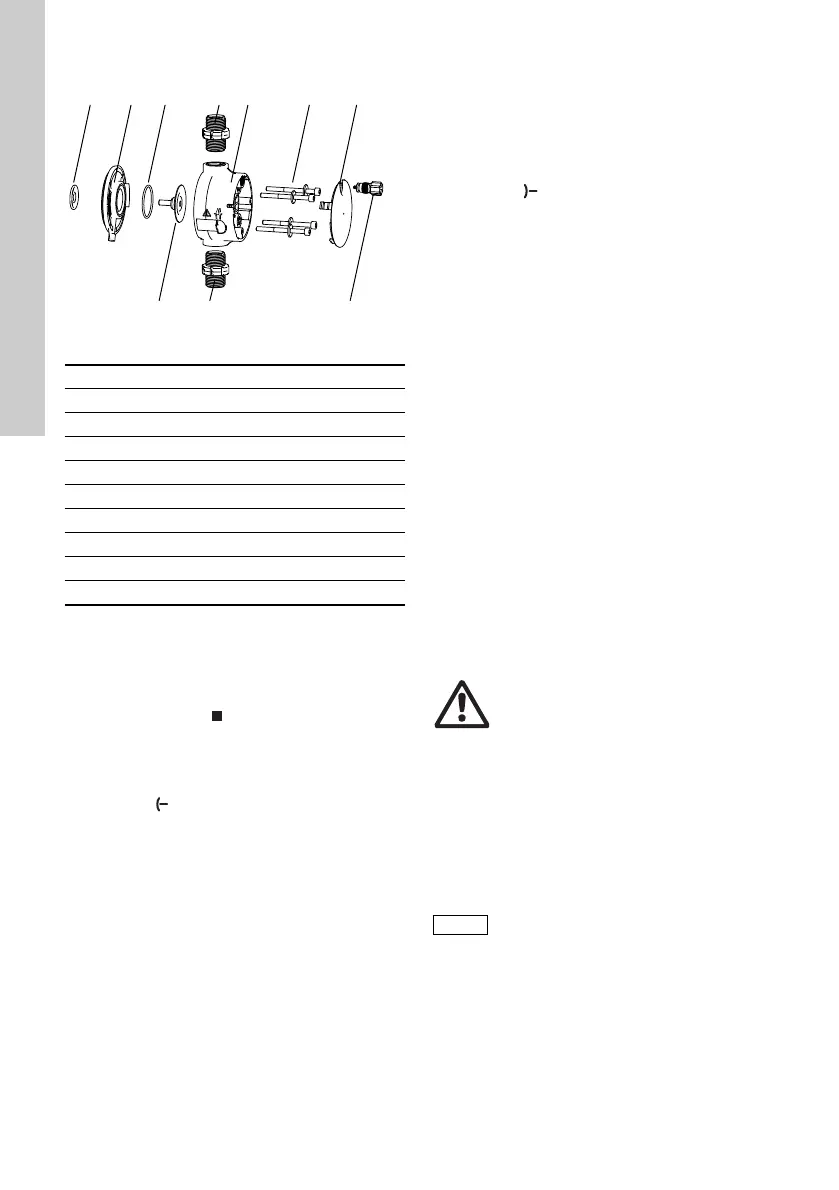
7.2.1 Dosing head overview
Fig. 40 Changing the diaphragm and valves
7.2.2 Dismantling the diaphragm and valves
1. Make system pressureless.
2. Empty dosing head before maintenance and
flush it if necessary.
3. Set pump to ’Stop’ operational state using the
’Start/stop key’.
4. Press the ’Start/stop’ and ’100 %’ keys at the
same time to put the diaphragm into ’out’
position.
– Symbol must be displayed as the
operational state (see fig. 14).
5. Take suitable steps to ensure that the returning
liquid is safely collected.
6. Dismantle suction, pressure and deaeration
hose.
7. Dismantle valves on suction and discharge
side (5, 6).
8. Remove the cover (9).
9. Undo screws (8) on the dosing head (7) and
remove with discs.
10.Remove the dosing head (7).
11. Unscrew diaphragm (4) counter-clockwise and
remove with flange (2).
7.2.3 Reassembling the diaphragm and valves
1. Attach flange (2) correctly and screw on new
diaphragm (4) clockwise.
– Make sure that the O-ring (3) is seated
correctly!
2. Press the ’Start/stop’ and ’100 %’ keys at the
same time to put the diaphragm into ’in’ position.
– Symbol must be displayed as the
operational state (see fig. 14).
3. Attach the dosing head (7).
4. Install screws with discs (8) and cross-tighten.
– Torque: 3 Nm.
5. Attach the cover (9).
6. Install new valves (5, 6).
– Do not interchange valves and pay attention to
direction of arrow.
7. Connect suction, pressure and deaeration hose
(see section 4.2 Hydraulic connection)
8. Press the ’Start/Stop’ key to leave the service
mode.
9. Deaerate dosing pump (see section
5.2 Deaerating the pump).
10. Please observe the notes on commissioning in
section 5. Commissioning!
7.3 Resetting the service system
After performing the service, the service system
must be reset using the ’Info > Reset service system’
function.
7.4 Repairs
After consulting Grundfos, please send the pump,
together with the safety declaration completed by a
specialist, to Grundfos. The safety declaration can
be found at the end of these instructions. It must be
copied, completed and attached to the pump.
If the above requirements are not met, Grundfos may
refuse to accept delivery of the pump. The shipping
costs will be charged to the sender.
TM04 1123 2110
1 Safety diaphragm
2Flange
3O-ring
4 Diaphragm
5 Valve on discharge side
6 Valve on suction side
7 Dosing head
8 Screws with discs
9 Cover
10 Deaeration valve
Warning
The pump housing must only be
opened by personnel authorised by
Grundfos!
Repairs must only be carried out by
authorised and qualified personnel!
Switch off the pump and disconnect it
from the voltage supply before carrying
out maintenance work and repairs!
If the pump has been used to dose
toxic liquids or liquids hazardous to
health, the pump must be cleaned prior
to dispatch!