English (GB)
32
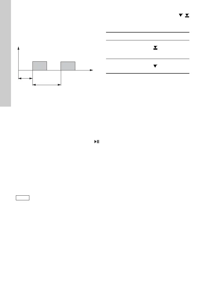
Timer, cycle (relay 2)
For the ’Relay 2 > Timer cycle’ function, set the
following parameters:
•Dosing time (t
1
)
• Start delay (t
2
)
•Cycle time (t
3
)
Fig. 37 Diagram
Timer, week (relay 2)
This function saves up to 16 relay on-times for a
week. The following settings can be made for each
relay switching operation in the ’Relay 2 >
Timer Week’ menu:
• Procedure (No.)
• On-time (duration)
• Start time
• Weekdays.
6.16.2 External stop
The pump can be stopped via an external
pulse, e. g. from a control room. When activating the
external stop pulse, the pump switches from the
operational state ’Running’ into the operational state
’Standby’. The corresponding symbol appears in the
Signal/error display (see section 6.2.2 Operating
states).
The contact type is factory-set to closed contact
(=>NO). In the ’Setup > Inputs/outputs > External
stop’ menu, the setting can be changed to open
contact (=>NC).
6.16.3 Empty and low-level signals
In order to monitor the filling level in the
tank, a dual-level sensor can be connected to the
pump. The pump responds to the signals as follows:
Both signal inputs are allocated to the closed contact
(=>NO) in the factory. They can be re-allocated in
the ’Setup > Inputs/outputs’ menu to open contact
(=>NC).
6.17 Basic settings
All settings can be reset to the settings default upon
delivery in the ’Setup > Basic settings’ menu.
Selecting ’Save customer settings’ saves the current
configuration to the memory. This can then be
activated using ’Load customer settings’ .
The memory always contains the previously saved
configuration. Older memory data is overwritten.
TM04 1124 2110
Frequent disengagement from the
mains voltage, e. g. via a relay, can
result in damage to the pump
electronics and to the breakdown of the
pump. The dosing accuracy is also
reduced as a result of internal start
procedures.
Do not control the pump via the mains
voltage for dosing purposes!
Only use the ’External stop’ function to
start and stop the pump!
Sensor signal Pump status
Low level
• Display is yellow
• flashes
• Pump continues
running
Empty
• Display is red
• flashes
• Pump stops