English (GB)
27
6.7 FlowControl
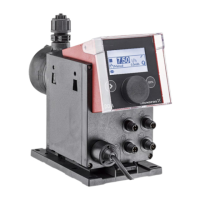
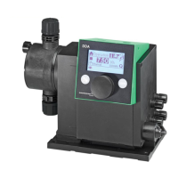
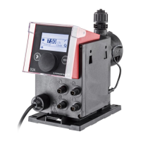
FC/FCM control variant.
This function is used to monitor the dosing process.
Although the pump is running, various influences
e. g. air bubbles, can cause a reduced flow or even
stop the dosing process. In order to guarantee
optimum process safety, the enabled FlowControl
function directly detects and indicates the following
errors and deviations:
• Overpressure
• Damaged discharge line
• Air in the dosing chamber
•Cavitation
• Suction valve leakage
• Discharge valve leakage.
The occurrence of a fault is indicated by the 'eye'
symbol flashing. The faults are displayed in the
’Alarm’ menu (see section 8. Faults).
FlowControl works with a maintenance-free sensor
in the dosing head. During the dosing process, the
sensor measures the current pressure and
continuously sends the measured value to the
microprocessor in the pump. An internal indicator
diagram is created from the current measured values
and the current diaphragm position (stroke length).
Causes for deviations can be identified immediately
by aligning the current indicator diagram with a
calculated optimum indicator diagram. Air bubbles in
the dosing head reduce e. g. the discharge phase
and consequently the stroke volume (see fig. 33).
Setting FlowControl
The ’FlowControl’ function is set using the two
parameters ’Sensitivity’ and ’Delay’ in the ’Setup >
FlowControl’ menu.
Sensitivity
In 'Sensitivity’ the deviation in stroke volume, which
will result in an error message, is set in percent.
Delay
The ’Delay’ parameter is used to define the time
period until an error message is generated: ’short’,
’medium’ or ’long’. The delay depends on the set
dosing flow and therefore cannot be measured in
strokes or time.
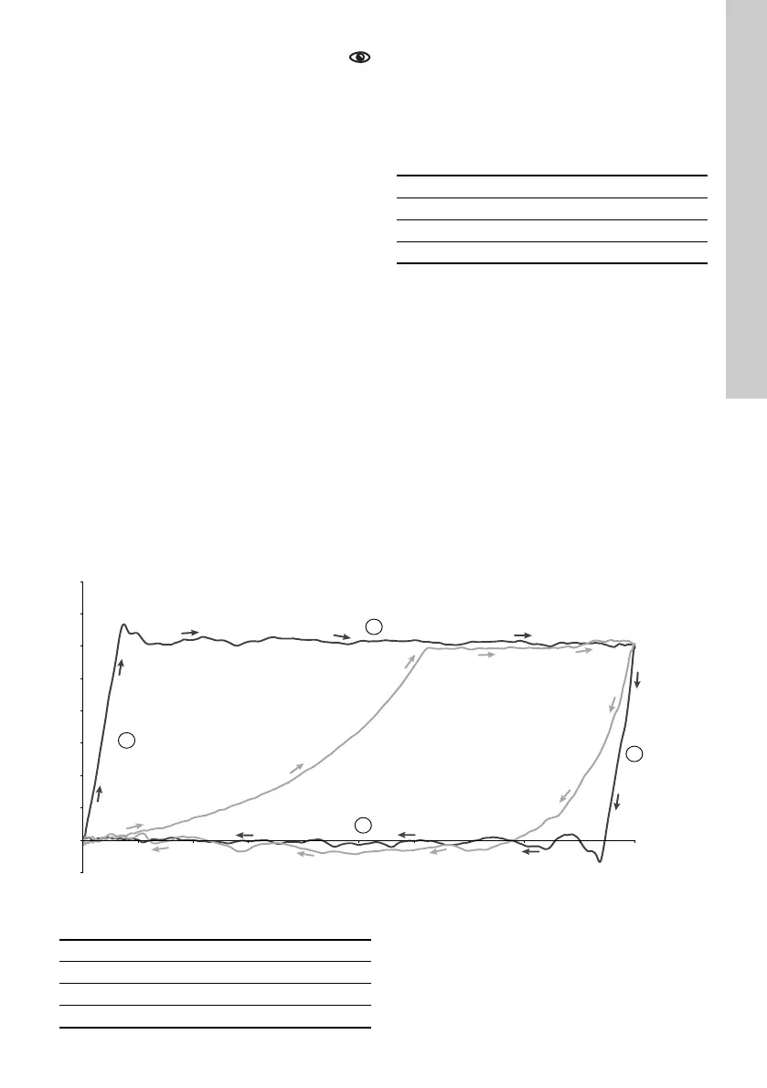
Fig. 33 Indicator diagram
Sensitivity Deviation
Low approx. 70 %
Medium approx. 50 %
High approx. 30 %
TM04 1610 1710
Pressure
Stroke
length
Trouble-free dosing
stroke
Faulty dosing stroke: Air
bubbles in the dosing
head
1 Compression phase
2 Discharge phase
3 Expansion phase
4 Suction phase