4. Installation
40 PNEG-2343 U-Trough Free Flow Unloading System
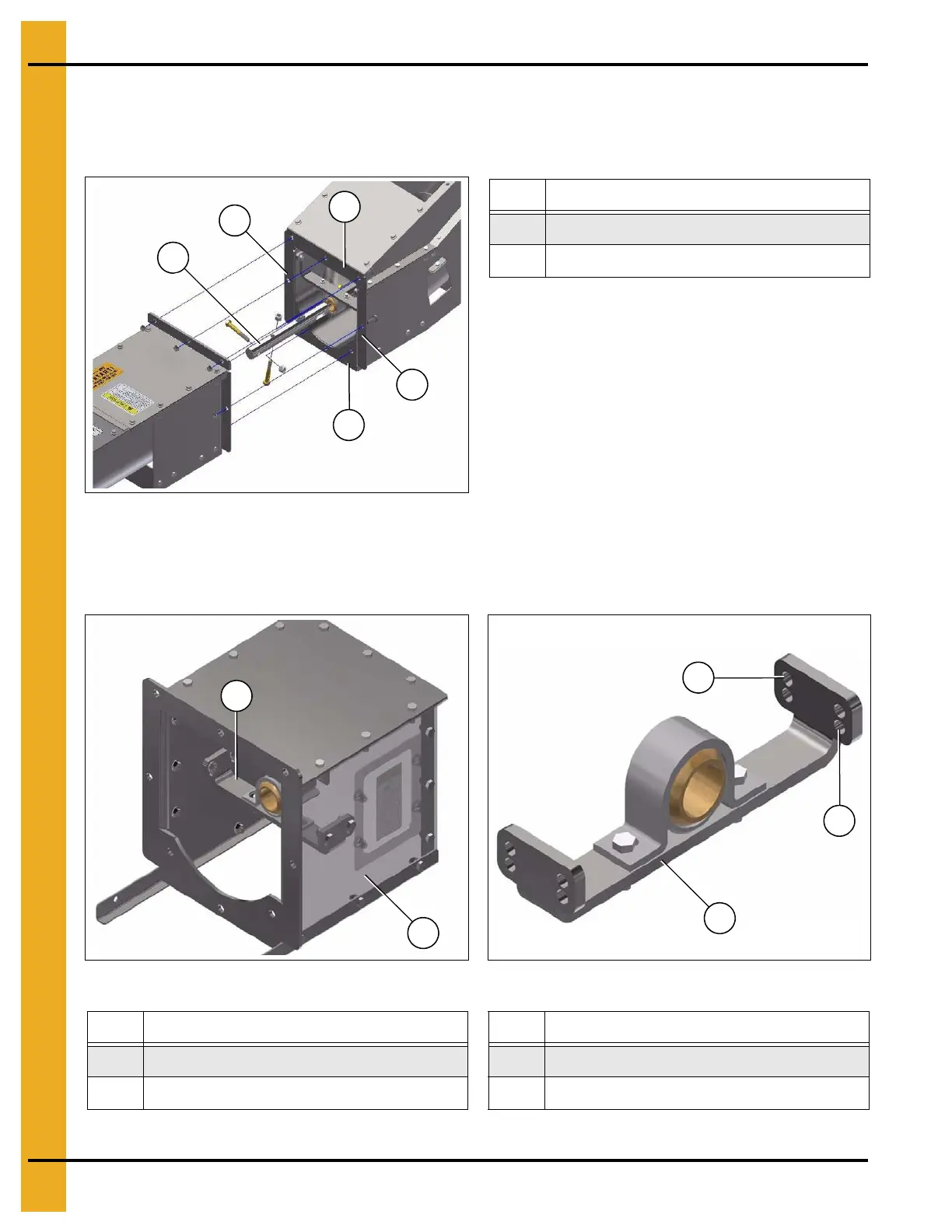
3. Install the incline elbow assembly on the end of the unloader. Insert the incline shaft (98) into the flight
bushing. Secure the incline elbow assembly to the unloader end by installing the eight nuts and bolts
remove in Step 1 around the perimeter of the box flange (94). Install the two 3-1/2" bolts and nuts in
the flight bushing to couple the flighting. (See Figure 4BB.)
Figure 4BB
4. Prepare the powerhead (41) for installation. Move the hanger bushing bracket (99) up 1/2" by
removing the four bolts, securing the hanger bushing bracket (99) and re-installing them using the
lower set of holes (101). (See Figure 4BC and Figure 4BD.)
Figure 4BC Figure 4BD
Ref # Description
94 Box Flange Perimeter
98 Incline Shaft (Shown out of normal position)
Ref # Description Ref # Description
41 Powerhead 100 Upper Holes
99 Hanger Bushing Bracket
101 Use Lower Holes Instead