4. Installation
PNEG-2343 U-Trough Free Flow Unloading System 41
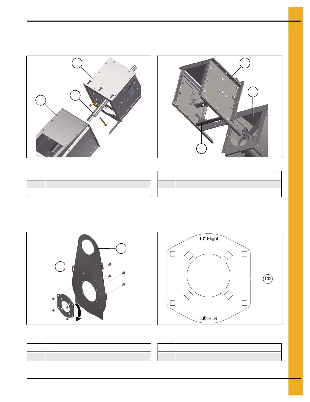
5. Bolt the powerhead (41) onto the end of the incline elbow assembly (97) with the eight bolts removed
previously. Ensure the discharge gate seal (95) is re-installed during this step. Insert the powerhead
shaft (91) into the incline flight bushing and secure it with two 3-1/2" bolts. (See Figure 4BE and
Figure 4BF.)
Figure 4BE Figure 4BF
6. Prepare polyshield plate assembly (81) for installation by un-bolting the bearing plate (102) and
rotate it 180°. Re-install the bearing plate (102). The words “10" FLIGHT” should now be upright.
(See Figure 4BG and Figure 4BH.)
NOTE: You can now proceed with typical powerhead installation as shown on Page 35.
Figure 4BG Figure 4BH Correct orientation of Bearing Plate for
Incline Elbow
7. Re-install the middle lid on the incline elbow, removed in step 2.
Ref # Description Ref # Description
41 Powerhead 95 Discharge Gate Seal
91 Powerhead Shaft
97 Incline Elbow Assembly
Ref # Description Ref # Description
81 Polyshield Plate Assembly 102 Bearing Plate