PART 1
VISUAL INSPECTION
When it becomes necessary to test or troubleshoot a
generator, it is a good practice to complete a thorough
visual inspection. Remove the access covers and look
closely for any obvious problems. Look for the follow-
ing:
• Burned or broken wires, broken wire connectors,
damaged mounting brackets, etc.
• Loose or frayed wiring insulation, loose or dirty con
-
nections.
• Check that all wiring is well clear of rotating parts.
• Verify that the Generator properly connected for the
correct rated voltage. This is especially important on
new installations. See Section 1.2, “AC Connection
Systems”.
• Look for foreign objects, loose nuts, bolts and other
fasteners.
• Clean the area around the Generator. Clear away
paper, leaves, snow, and other objects that might
blow against the generator and obstruct its air
openings.
INSULATION RESISTANCE
The insulation resistance of stator and rotor windings
is a measurement of the integrity of the insulating
materials that separate the electrical windings from
the generator steel core. This resistance can degrade
over time or due to such contaminants as dust, dirt,
oil, grease and especially moisture. In most cases,
failures of stator and rotor windings is due to a break-
down in the insulation. And, in many cases, a low insu-
lation resistance is caused by moisture that collects
while the generator is shut down. When problems are
caused by moisture buildup on the windings, they can
usually be corrected by drying the windings. Cleaning
and drying the windings can usually eliminate dirt and
moisture built up in the generator windings.
THE MEGOHMMETER
GENERAL:
A megohmmeter, often called a “megger”, consists of
a meter calibrated in megohms and a power supply.
Use a power supply of 500 volts when testing stators
or rotors. DO NOT APPLY VOLTAGE LONGER THAN
ONE (1) SECOND.
TESTING STATOR INSULATION:
All parts that might be damaged by the high meg-
ger voltages must be disconnected before testing.
Isolate all stator leads (Figure 8) and connect all of
the stator leads together. FOLLOW THE MEGGER
MANUFACTURER’S INSTRUCTIONS CAREFULLY.
Use a megger power setting of 500 volts. Connect
one megger test lead to the junction of all stator
leads, the other test lead to frame ground on the sta-
tor can. Read the number of megohms on the meter.
The MINIMUM acceptable megger reading for stators
may be calculated using the following formula:
EXAMPLE: Generator is rated at 120 volts AC.
Divide “120” by “1000” to obtain “0.12”. Then add
“1” to obtain “1.12” megohms. Minimum Insulation
resistance for a 120 VAC stator is 1.12 megohms.
If the stator insulation resistance is less than the cal
-
culated minimum resistance, clean and dry the stator.
Then, repeat the test. If resistance is still low, replace
the stator.
Use the Megger to test for shorts between isolated
windings as outlined “Stator Insulation Tests”.
Also test between parallel windings. See “Test
Between Windings” on next page.
TESTING ROTOR INSULATION:
Apply a voltage of 500 volts across the rotor posi-
tive (+) slip ring (nearest the rotor bearing), and
a clean frame ground (i.e. the rotor shaft). DO
NOT EXCEED 500 VOLTS AND DO NOT APPLY
VOLTAGE LONGER THAN 1 SECOND. FOLLOW
THE MEGGER MANUFACTURER’S INSTRUCTIONS
CAREFULLY.
ROTOR MINIMUM INSULATION RESISTANCE:
1.5 megohms
CAUTION: Before attempting to measure
Insulation resistance, first disconnect and
Isolate all leads of the winding to be tested.
Electronic components, diodes, surge protec-
tors, relays, voltage regulators, etc., can be
destroyed if subjected to high megger volt-
ages.
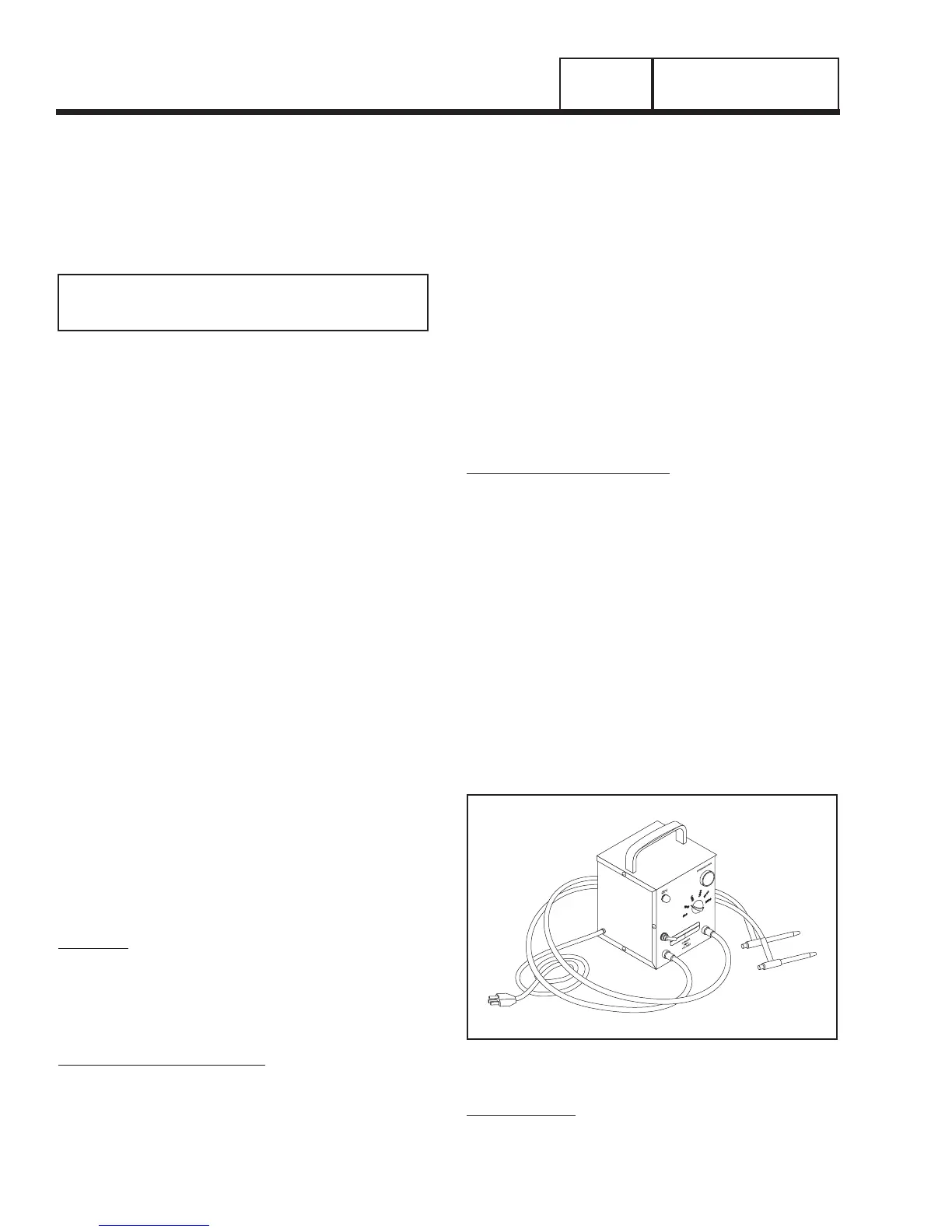
Figure 7. One Type of Hi-Pot Tester
HI-POT TESTER:
A “Hi-Pot” tester is shown in Figure 7. The model
shown is only one of many that are commercially
available. The tester shown is equipped with a voltage
Page 20
GENERAL INFORMATION
SECTION 1.4
TESTING, CLEANING AND DRYING
MINIMUM INSULATION
GENERATOR RATED VOLTS
RESISTANCE =
__________________________
+1
(in “Megohms”)
1000