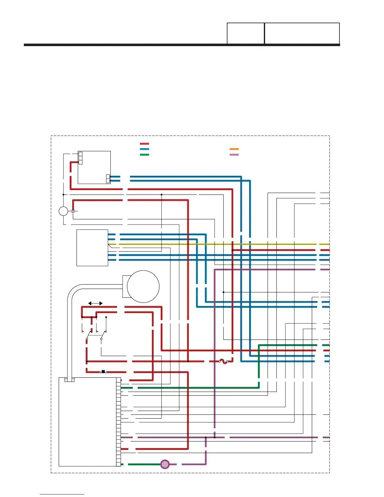
= 12 VDC ALWAYS PRESENT
=AC VOLTAGE
= GROUND FOR CONTROL PURPOSES
= 12 VDC DURING CRANKING ONLY
= 12 VDC DURING ENGINE RUN CONDITION
225B
224B
13
15
56
16
86
15A
224
15B
PRINTED CIRCUIT
11
13
14
12
CONTROL
BOARD
5
8
9
10
6
7
J1
2
3
4
1
VOLTAGE
REGULATOR
ELECTRONIC
MANUAL
SW2
AUTO
23915
SW1
194
194 15A
15A
194
6
2
4
0
4
11
22
56
0
0
13
0
CHARGER
2
1
0
BATTERY
3
1
2
13
18
85
239
56
4
23
14
14
56
15A
239
15
194
4
F1
15
0
22 11
16 0
225
86 LC2
14
0
225B
23
225B
224B
194
0
86
2
14
16
13
4
6
0
0
224B
85
18
86
13
GOVERNOR
ACTUATOR
J2
18
1823
224
0
0
11
22
15
15
15
16
17
18
19
20
21
22
23
LC1
LC2
85
85LC1
LC2
LC1
14
225
15B
0
90 CS
14
14
SCR
Page 90
PART 4
DC CONTROL
SECTION 4.2
OPERATIONAL ANALYSIS
INITIAL TRANSFER TO THE “STANDBY” SOURCE
The generator is running, the circuit board’s “engine warm-up timer” is timing, and generator AC output is avail-
able to transfer switch terminal lugs E1 and E2 and to the open contacts on the transfer relay. Initial transfer to the
STANDBY power supply may be briefly described as follows:
• 12 volts DC output is delivered to the transfer relay (TR) actuating coil, via Wire 194, and terminal A of the
transfer relay (TR) in the transfer switch. This 12 volts DC circuit is completed back to the board, via transfer
relay terminal B, and Wire 23. However, circuit board action holds the Wire 23 circuit open to ground and the
transfer relay (TR) is de-energized.
• When the circuit board’s “engine warm-up timer” times out, circuit board action completes the Wire 23 circuit to
ground. The transfer relay then energizes and its normally open contacts close.