= 12 VDC ALWAYS PRESENT
=AC VOLTAGE
= GROUND FOR CONTROL PURPOSES
= 12 VDC DURING CRANKING ONLY
= 12 VDC DURING ENGINE RUN CONDITION
225B
224B
13
15
56
16
86
15A
224
15B
PRINTED CIRCUIT
11
13
14
12
CONTROL
BOARD
5
8
9
10
6
7
J1
2
3
4
1
VOLTAGE
REGULATOR
ELECTRONIC
MANUAL
SW2
AUTO
23915
SW1
194
194 15A
15A
194
6
2
4
0
4
11
22
56
0
0
13
0
CHARGER
2
1
0
BATTERY
3
1
2
13
18
85
239
56
4
23
14
14
56
15A
239
15
194
4
F1
15
0
22 11
16 0
225
86 LC2
14
0
225B
23
225B
224B
194
0
86
2
14
16
13
4
6
0
0
224B
85
18
86
13
GOVERNOR
ACTUATOR
J2
18
1823
224
0
0
11
22
15
15
15
16
17
18
19
20
21
22
23
LC1
LC2
85
85LC1
LC2
LC1
14
225
15B
0
90 CS
14
14
SCR
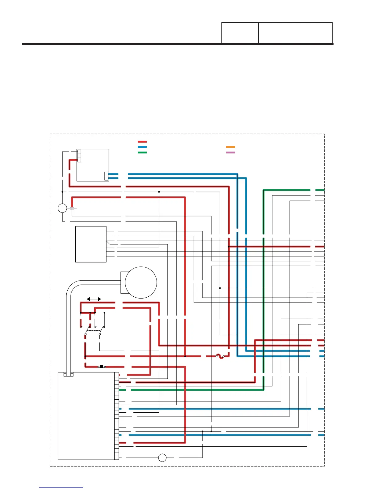
Page 94
ENGINE SHUTDOWN
Following retransfer back to the utility source, an “engine cool-down timer” on the circuit board starts timing. When
that timer has timed out (approximately one minute), circuit board action will de-energize the circuit board’s run
relay. The following events will then occur:
• The DC circuit to Wire 14 and the fuel solenoids (FS1 & FS2) will be opened. The fuel solenoids will de-ener
-
gize and close to terminate the engine fuel supply.
PART 4
DC CONTROL
SECTION 4.2
OPERATIONAL ANALYSIS