Page 4
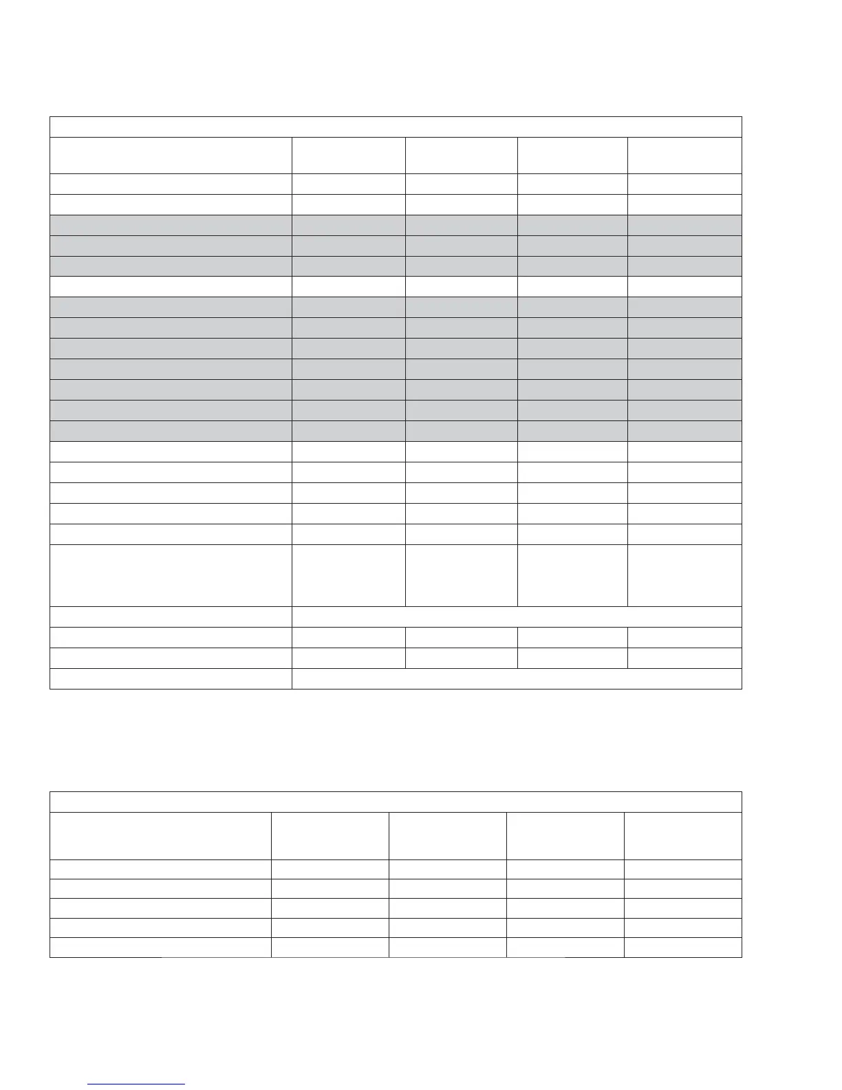
GENERATOR
Model
005240 & 005280 005241 & 005281 005242 & 005282
005243 & 005283
005244 & 005284
Rated Max. Continuous Power Capacity (Watts*) 6,000 NG/7,000 LP 9,000 NG/10,000 LP 13,000 NG/13,000 LP 15,000 NG/16,000 LP
Rated Voltage 120/240 120/240 120/240 120/240
Rated Max. Continuous Load Current (Amps)
120 Volts** 50.0 NG/58.3 LP 75.0 NG/83.3 LP 108.3 NG/108.3 LP 125 NG/133.3 LP
240 Volts 25.0 NG/29.2 LP 37.5 NG/41.7 LP 54.1 NG/54.1 LP 52.5 NG/66.6 LP
Main Line Circuit Breaker 30 Amp 45 Amp 55 Amp 65 Amp
Circuits***
50A, 240V - - - 1
40A, 240V - - 1 1
30A, 240V 1 1 1 -
20A, 240V - 1 - 1
20A, 120V 1 3 3 5
15A, 120V 5 3 5 5
Phase 1 1 1 1
Number of Rotor Poles 2 2 2 2
Rated AC Frequency 60 Hz 60 Hz 60 Hz 60 Hz
Power Factor 1 1 1 1
Recommended Air Filter Part # 0C8127 Part # 0E9581 Part # 0C8127 Part # 0C8127
Battery Requirement Group 26
12 Volts and
350 Cold-cranking
Amperes Minimum
Group 26
12 Volts and
525 Cold-cranking
Amperes Minimum
Group 26
12 Volts and
525 Cold-cranking
Amperes Minimum
Group 26
12 Volts and
525 Cold-cranking
Amperes Minimum
Battery Warming Blanket 0F6148DSRV
Weight (Unit Only) 336 Pounds 375 Pounds 425.5 Pounds 445 & 414 Pounds
Enclosure Steel/Aluminum
Normal Operating Range -20°F (-28.8°C) to 104°F (40°C)
* Maximum wattage and current are subject to and limited by such factors as fuel Btu content, ambient temperature, altitude, engine power and condition, etc. Maximum power
decreases about 3.5 percent for each 1,000 feet above sea level; and also will decrease about 1 percent for each 6° C (10° F) above 16° C (60° F) ambient temperature.
** Load current values shown for 120 volts are maximum TOTAL values for two separate circuits. The maximum current in each circuit must not exceed the value stated for 240 volts.
*** Circuits to be moved from main panel to transfer switch load center must be protected by same size breaker. For example, a 15 amp circuit in main panel must be a 15 amp circuit in
transfer switch.
STATOR WINDING RESISTANCE VALUES / ROTOR RESISTANCE
005240, 005280
(6/7 kW)
005241, 005281
(9/10 kW)
005242, 005282
(13/13 kW)
005243, 005283
005244, 005284
(15/16 kW)
Power Winding: Across 11 & 22 0.223-0.259 ohms 0.144 ohms 0.115 ohms 0.080 ohms
Power Winding: Across 33 & 44 0.223-0.259 ohms 0.144 ohms 0.115 ohms 0.080 ohms
Excitation Winding: Across2&6 1.528-1.769 ohms 1.238 ohms 1.256 ohms 1.092 ohms
Battery Charge Winding: Across 66 & 77 0.146-0.169 ohms 0.158 ohms 0.164 ohms 0.130 ohms
Rotor Resistance 11.88-13.76 ohms 11.8 ohms 12.6 ohms 22.0 ohms
SPECIFICATIONS