PART 2
TEST 6 - CHECK FIELD BOOST
DISCUSSION:
See “Field Boost Circuit” in Section 2.2. Field boost
current (from the circuit board) is available to the rotor
only while the engine is cranking. Loss of field boost
output to the rotor may or may not affect power wind-
ing AC output voltage. The following facts apply:
• A small amount of voltage must be induced into the
DPE winding to turn the voltage regulator on.
• If rotor residual magnetism is sufficient to induce
a voltage into the DPE winding that is high
enough to turn the voltage regulator on, regula-
tor excitation current will be supplied even if field
boost has failed. Normal AC output voltage will
then be supplied.
• If rotor residual magnetism has been lost or is not
sufficient to turn the regulator on, and field boost
has also been lost, excitation current will not be
supplied to the rotor. Generator AC output voltage
will then drop to zero or nearly zero.
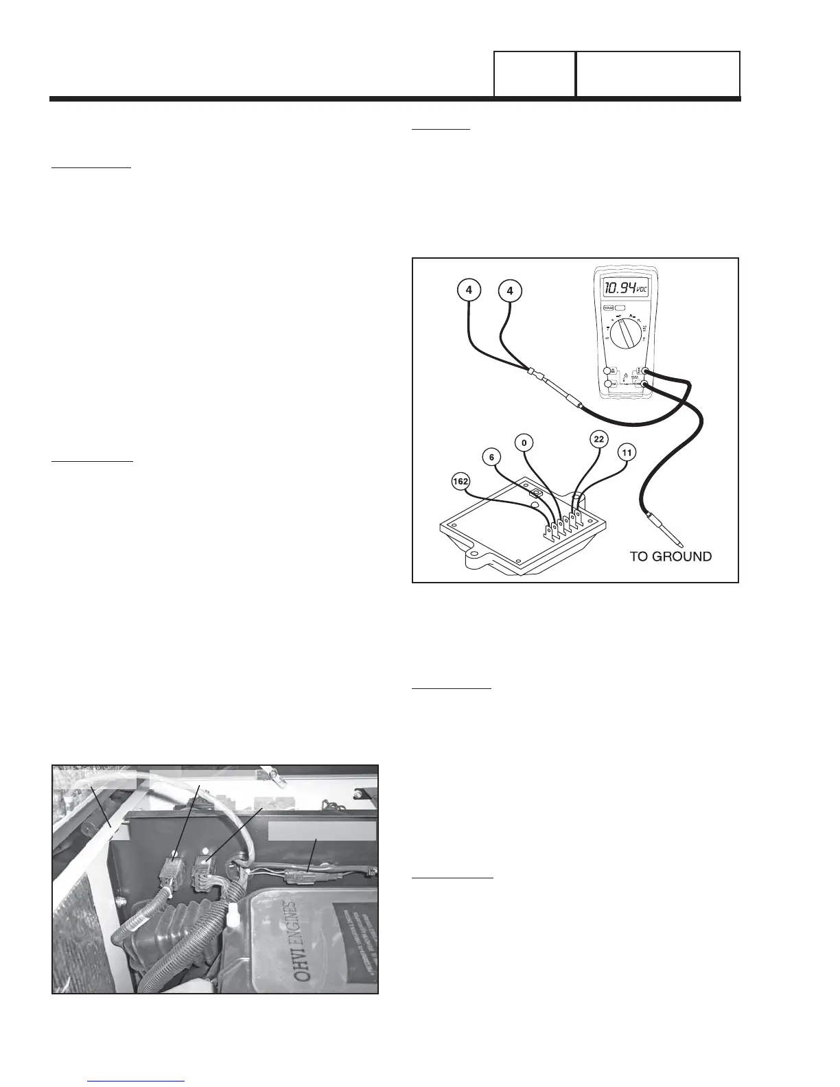
PROCEDURE:
1. Disconnect Wire 4 from the voltage regulator, third termi-
nal from the top (see Figure 4).
2. Set a VOM to read DC volts.
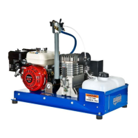
3. Disconnect C2 Connector from the control panel (see
Figure 3).
4. Connect the positive (+) VOM test probe to the terminal
end of disconnected Wire 4.
5. Connect the common (-) VOM test probe to the
grounding lug.
6. Crank the engine while observing the VOM reading.
While the engine is cranking, the VOM should read
approximately 9-10 volts DC. When engine is not crank-
ing, VOM should indicate “zero” volts (see Figure 4).
7. Reconnect the C2 Connector and Wire 4.
BACK PANEL
C1 CONNECTOR
C2 CONNECTOR
C3 CONNECTOR
Figure 3. C2 Connector Location
RESULTS:
1. If normal field boost voltage is indicated in Step 6,
replace the voltage regulator.
2. If normal field boost voltage is NOT indicated in Step 6,
check Wire 4 (between regulator and circuit board) for
open or shorted condition. If wire is good, replace the
circuit board.
Figure 4. Field Boost Test Points
TEST 7 - TESTING THE STATOR WITH A VOM
DISCUSSION:
A Volt-OHM-Milliammmeter (VOM) can be used to test
the stator windings for the following faults:
• An open circuit condition
• A “short-to-ground” condition
• A short circuit between windings
Note: The resistance of stator windings is very
low. Some meters will not read such a low resis-
tance, and will simply indicate CONTINUITY.
Recommended is a high quality, digital type meter
capable of reading very low resistances.
PROCEDURE:
1. Disconnect stator leads 11 and 44 from the main circuit
breaker.
2. Disconnect stator leads 22 and 33 from the neutral con-
nection separate the leads.
3. Disconnect C2 Connector from the side of the control
panel (see Figure 3).
4. Make sure all of the disconnected leads are isolated
Page 42
AC GENERATORS
SECTION 2.4
DIAGNOSTIC TESTS