a.If voltage is present, proceed to Step 7.
b. If voltage is not present, repair wiring between
transfer switch and generator control panel.
7. Connect the positive (+) test lead to Wire 23 located in
the J1 Connector Pin Location 3, connected to the cir-
cuit board (see Figure 3, Section 4.1).
a.If voltage is present, proceed to Step 8.
b. If voltage is not present, repair wiring between
(ICT and J1 Connector).
8. Turn off utility power to transfer switch, simulating a utility
failure.
a.Generator starts and transfer occurs, discon-
tinue tests.
b. Generator starts and transfer does not occur.
With the generator running and utility off, ground
Wire 23 in the control panel at interconnection
terminals (ICT) or at the terminal strip. If trans-
fer occurs replace circuit board.
9. Connect the negative (-) test lead to the ground lug in
the generator control panel. Connect the positive (+) test
lead to Wire 194 in the generator control panel at the
interconnection terminals (ICT) or at the terminal strip.
a.If the voltage is present, repair wiring between
ICT (or terminal strip) and transfer switch
b. If voltage is not present, proceed to Step 10.
10.
Connect the positive (+)
test lead to Wire 194
located
at AUTO-OFF-MANUAL switch (SW1) (see Figure 3,
Section 4.1).
a.If voltage is present, repair wiring betweenJ1
Connector and ICT (or terminal strip).
b. If voltage is not present, perform Test 44. Repair
or replace SW1 or wiring as needed.
TEST 27- CHECK VOLTAGE AT TERMINAL
LUGS N1, N2
DISCUSSION:
If retransfer to the “Utility” power source side is to
occur, utility source voltage must be available to
Terminal Lugs N1 and N2 of the transfer mechanism.
In addition, If that source voltage is not available to
NI/N2 terminals, automatic startup and transfer to
STANDBY will occur when the generator AUTO-OFF-
MANUAL switch is set to AUTO. This test will prove
that “Utility” voltage is available to those terminals, or
is not available. It is the first test in a series of tests
that should be accomplished when (a) retransfer back
to “Utility” does not occur, or (b) startup and transfer
occurs unnecessarily.
DANGER: PROCEED WITH CAUTION! HIGH
AND DANGEROUS VOLTAGES ARE PRESENT
AT TERMINAL LUGS N1/N2. CONTACT WITH
HIGH VOLTAGE TERMINALS WILL RESULT
IN DANGEROUS AND POSSIBLY LETHAL
ELECTRICAL SHOCK. DO NOT ATTEMPT
THIS TEST WHILE STANDING ON WET OR
DAMP GROUND, WHILE BAREFOOT, OR
WHILE HANDS OR FEET ARE WET.
PROCEDURE:
1. Make sure that all main line circuit breakers in the utility
line to the transfer switch are “On” or “Closed.”
2. Test for utility source line-to-line voltage across Terminal
Lugs N1 and N2 (see Figure 1). Normal utility source
voltage should be indicated.
RESULTS:
1. If low or no voltage is indicated, find the cause of the
problem and correct.
2. If normal utility source voltage is indicated, go on to
Test 28.
3. For Problem 14 ONLY, if voltage is good, repair or
replace Wire N1A/N2A between Transfer Switch Lugs
N1/N2 and Fuse Holder connections.
TEST 28 - CHECK VOLTAGE AT UTILITY 1 AND
UTILITY 2 TERMINALS
The UTILITY 1 and UTILITY 2 terminals in the trans-
fer switch deliver utility voltage “sensing” to a circuit
board. If voltage at the terminals is zero or low, stand-
by generator startup and transfer to the “Standby”
source will occur automatically as controlled by the
circuit board. A zero or low voltage at these terminals
will also prevent retransfer back to the “Utility” source.
PROCEDURE:
With utility source voltage available to terminal lugs
N1 and N2, use an AC voltmeter or a VOM to test for
utility source line-to-line voltage across terminal block
UTILITY 1 and UTILITY 2 terminals. Normal line-to-
line utility source voltage should be indicated.
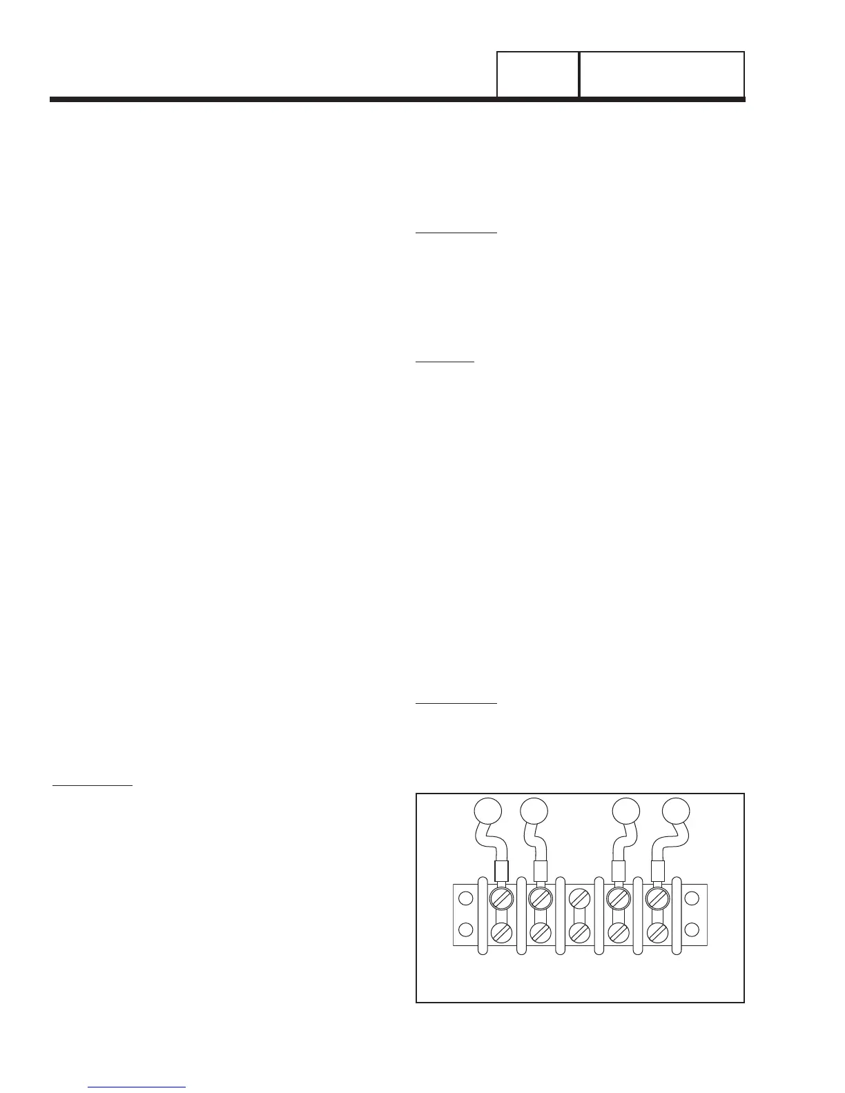
UTILITY
1
UTILITY
2
23
194
N1 N2 23 194
Figure 4. Transfer Switch Terminal Block
PART 3
Page 70
“V-TYPE” PREPACKAGED
TRANSFER SWITCHES
SECTION 3.4
DIAGNOSTIC TESTS