PART 2
RESULTS:
1. Stator winding resistance values is a test of winding
continuity and resistance. If a very high resistance or
INFINITY is indicated, the winding is open or partially
open.
2. Testing for a “grounded” condition: Any resistance read-
ing indicates the winding is grounded.
3. Testing for a “shorted” condition: Any
resistance read-
ing
indicates the winding is shorted.
4. If the stator tests good and wire continuity tests good ,
perform “Insulation Resistance Test” in Section 1.4.
5. If any test of wire continuity failed in the control panel,
repair or replace the wire, terminal or pin connectors for
that associated wire as needed.
NOTE: Read Section 1.4, “Testing, Cleaning and
Drying” carefully. If the winding tests good, per-
form an insulation resistance test. If the winding
fails the insulation resistance test, clean and dry
the stator as outlined in Section 1.4. Then, repeat
the insulation resistance test. If the winding fails
the second resistance test (after cleaning and dry-
ing), replace the stator assembly.
TEST 8 - RESISTANCE CHECK OF
ROTOR CIRCUIT
DISCUSSION:
To verify the zero current draw reading and measure
the rotor circuit.
PROCEDURE:
1. Disconnect Wire 4 from the voltage regulator. It is locat-
ed 3rd terminal from the top of the volt regulator.
2. Set VOM to measure resistance.
3. Connect one test lead to Wire 4. Connect the other test
lead to a clean frame ground. Note the resistance reading.
Compare to specifications in the front of this manual.
RESULTS:
1. If the resistance reading is correct, check your VOM
meters fuse and repeat Test 4.
2. If INFINITY is measured on your VOM meter, go to
Test 9.
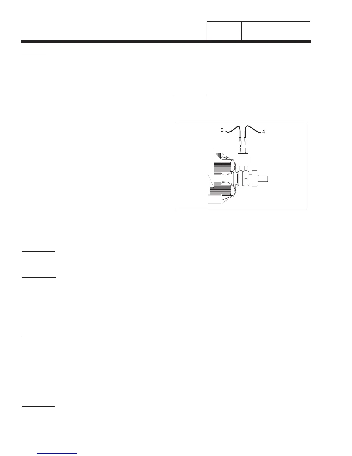
TEST 9 - CHECK BRUSHES AND SLIP RINGS
DISCUSSION:
The function of the brushes and slip rings is to pro-
vide for passage of excitation current from stationary
components to the rotating rotor. Brushes are made
of a special long lasting material and seldom wear
out or fail. However, slip rings can develop a tarnish or
film that can inhibit or offer a resistance to the flow of
electricity. Such a non-conducting film usually devel-
ops during non-operating periods. Broken or discon-
nected wiring can also cause loss of excitation current
to the rotor.
PROCEDURE:
1. Disconnect C2 Connector. Refer to Figure 3 on Page 40.
2. Set a VOM to measure resistance.
Figure 6. Checking Brushes and Slip Rings
3. Connect one meter test lead to Pin 7 (Wire 0) of the
C2 Connector (female side). Connect the other meter
test lead to Pin 8 (Wire 4) of the C2 Connector (female
side). Rotor resistance should be measured (see
Specifications in front of book). If rotor resistance is not
measured proceed to Step 4. If rotor resistance is mea-
sured proceed to Step 12. Refer to Figure 5.
4. See Figure 6. Carefully inspect brush wires; make sure
they are properly and securely connected.
5. Wire 0 from the negative (-) brush terminal connects to
Pin 7 of the C2 Connector.
Test this wire for an open condition. Remove Wire 0
from the brush assembly. Connect one meter test lead
to Wire 0. Connect the other test lead to Pin 7 (Wire
0) of the C2 Connector ( female side). CONTINUITY
should be measured. If INFINITY is measured repair or
replace Wire 0 between the brush assembly and the C2
Connector.
6. Wire 4 from the positive (+) brush terminal connects
to Pin 8 of the C2 Connector. Test this wire for an
open condition. Remove Wire 4 from the brush assem-
bly. Connect one meter test lead to Wire 4. Connect
the other meter test lead to Pin 8 (Wire 0) of the C2
Connector (female side). CONTINUITY should be mea-
sured. If INFINITY is measured repair or replace Wire 4
between the brush assembly and the C2 Connector.
Page 44
AC GENERATORS
SECTION 2.4
DIAGNOSTIC TESTS