AC GENERATORS
SECTION 2.4
DIAGNOSTIC TESTS
from each other and are not touching the frame during
the test.
5. Set a VOM to measure resistance.
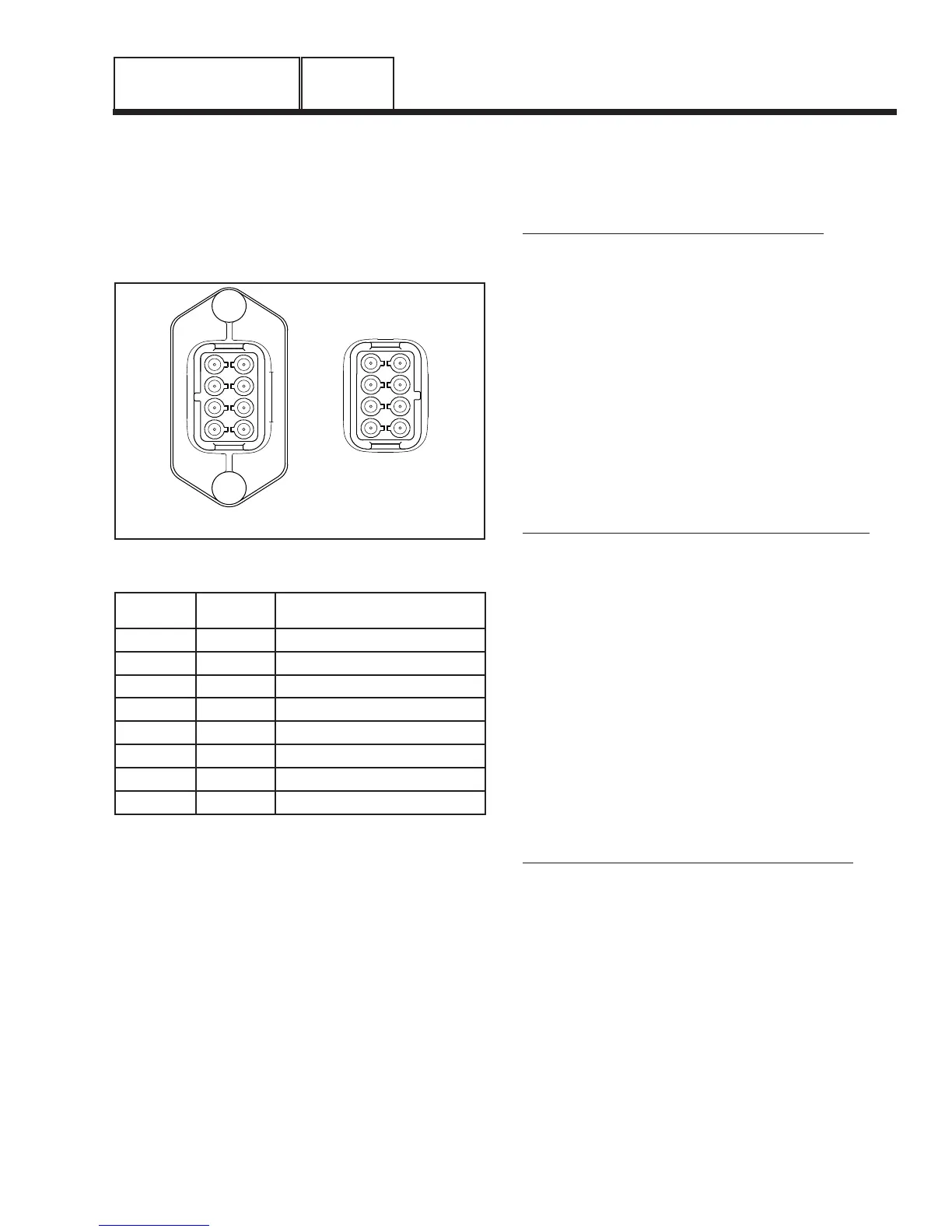
6. Refer to Figure 5 for pin locations of C2 Connector. Use
a large paper clip or similar metallic object to access
pins in C2 Connector (Female Side).
4
8
5
7
6
1
FEMALE SIDEMALE SIDE
2
3
4
8
5
7
6
1
2
3
Figure 5. C2 Connector Pin Locations
Pin
Location
Wire
Number
Winding
1 77 Battery Charge
2 66 Battery Charge
3 22 Sense Lead Power
4 11 Sense Lead Power
5 6 Excitation
6 2 Excitation
7 0 Ground
8 4 Positive to Brush
7. Connect one test lead to stator lead Wire 11. Connect
the other test lead to stator lead Wire 22 (power wind-
ing). Note the resistance reading and compare to the
specifications in the front of this manual.
8. Connect one test lead to stator lead Wire 33. Connect
the other test lead to stator lead Wire 44 (power wind-
ing). Note the resistance reading and compare to the
specifications in the front of this manual.
9. Connect one test lead to Pin 1. Connect the other test
lead to Pin 2 (battery charge winding). Note the resis-
tance reading, compare to specifications in the front of
this manual.
10.Connect one test lead to Pin 3. Connect the other test
lead to Pin 4 (power winding-sense leads). Note the
resistance reading, compare to specification in the front
of this manual.
11.Connect on test lead to Pin 5. Connect the other test
lead to Pin 6 (excitation winding). Note the resistance
reading, compare to specifications in the front of this
manual.
TEST WINDINGS FOR A SHORT TO GROUND:
12. Make sure all leads are isolated from each other and
are not touching the frame.
13. Connect one test lead to a clean frame ground. Connect
the other test lead to stator lead Wire 11.
a.The meter should read INFINITY.
b. Any reading other than INFINITY indicates a
“short-to-ground” condition.
14. Repeat Step 13 using stator lead Wire 33.
15. Repeat Step 13 using Pin 1.
16. Repeat Step 13 using Pin 3.
17. Repeat Step 13 using Pin 5.
TEST FOR A SHORT CIRCUIT BETWEEN WINDINGS:
18. Connect one test lead to stator lead Wire 11. Connect
the other test lead to stator lead Wire 33.
a.The meter should read INFINITY.
b. Any reading other than INFINITY indicates a
short circuit between windings.
19.Repeat Step 18 using stator lead Wire 11; Pin 1.
20.Repeat Step 18 using stator lead Wire 11; Pin 5.
21.Repeat Step 18 using stator lead Wire 33; Pin 1.
22.Repeat Step 18 using stator lead Wire 33; Pin 5.
23.Repeat Step 18 using Pin 1; Pin 3.
24.Repeat Step 18 using Pin 1; Pin 5.
25.Repeat Step 18 using Pin 3; Pin 5.
TEST CONTROL PANEL WIRES FOR CONTINUITY:
26.Disconnect the C2 Connector from the control panel.
Refer to Figure 5 for the pin locations (Male Side).
27.Connect one meter test lead to Pin 3 of the C2 Connector
(Male Side), connect the other test lead to Wire 22 at the
voltage regulator. CONTINUITY should be measured.
28.Connect one meter test lead to Pin 4 of the C2 Connector
(Male Side), connect the other test lead to Wire 11 at the
voltage regulator. CONTINUITY should be measured.
29.Connect one meter test lead to Pin 5 of the C2 Connector
(Male Side), connect the other test lead to Wire 6 at the
voltage regulator. CONTINUITY should be measured.
30. Connect one meter test lead to Pin 6 of the C2 Connector
(Male Side), connect the other test lead to Wire 2.
CONTINUITY should be measured at the voltage regulator.
PART 2
Page 43
 Loading...