AC GENERATORS
SECTION 2.4
DIAGNOSTIC TESTS
7. Connect one meter test lead to Wire 4 Connect the
other meter test lead to frame ground. INFINITY should
be measured. If CONTINUITY is measured a short
to ground exists on Wire 4 repair or replace Wire 4
between the brush assembly and the C2 Connector.
8. If CONTINUITY was measured in Steps 5 and 6 proceed
to Step 9.
9. Disconnect Wire 0 and Wire 4 from the brush assembly.
Remove the brush assembly from the bearing carrier.
Inspect the brushes for excessive wear, or damage.
10.Inspect the rotor slip rings. If they appear dull or tar-
nished, they may be polished with a fine sandpaper. DO
NOT USE METALLIC GRIT TO POLISH SLIP RINGS.
11.If brush assembly and slip rings look good proceed to
Test 10 ( Test Rotor Assembly)
12.Wire 0 connects from the C2 Connector to the control
panel ground lug. Connect one meter test lead to Pin
7 (Wire 0) of the C2 Connector (male side). Connect
the other meter test lead to the ground terminal in the
control panel. CONTINUITY should be measured. If
INFINITY is measured repair or replace Wire 0 between
the C2 Connector and the ground terminal.
13.Remove Wire 4 from the voltage regulator.
14.Connect one meter test lead to Pin 8 (Wire 4) of the
C2 Connector (male side). Connect the other meter
test lead to Wire 4 removed from the Voltage regula-
tor. CONTINUITY should be measured. If INFINITY
is measured repair or replace Wire 4 between the C2
Connector and the voltage regulator.
RESULTS:
1. Repair, replace or reconnect wires as necessary.
2. Replace any damaged slip rings or brush holder.
3. Clean and polish slip rings as required.
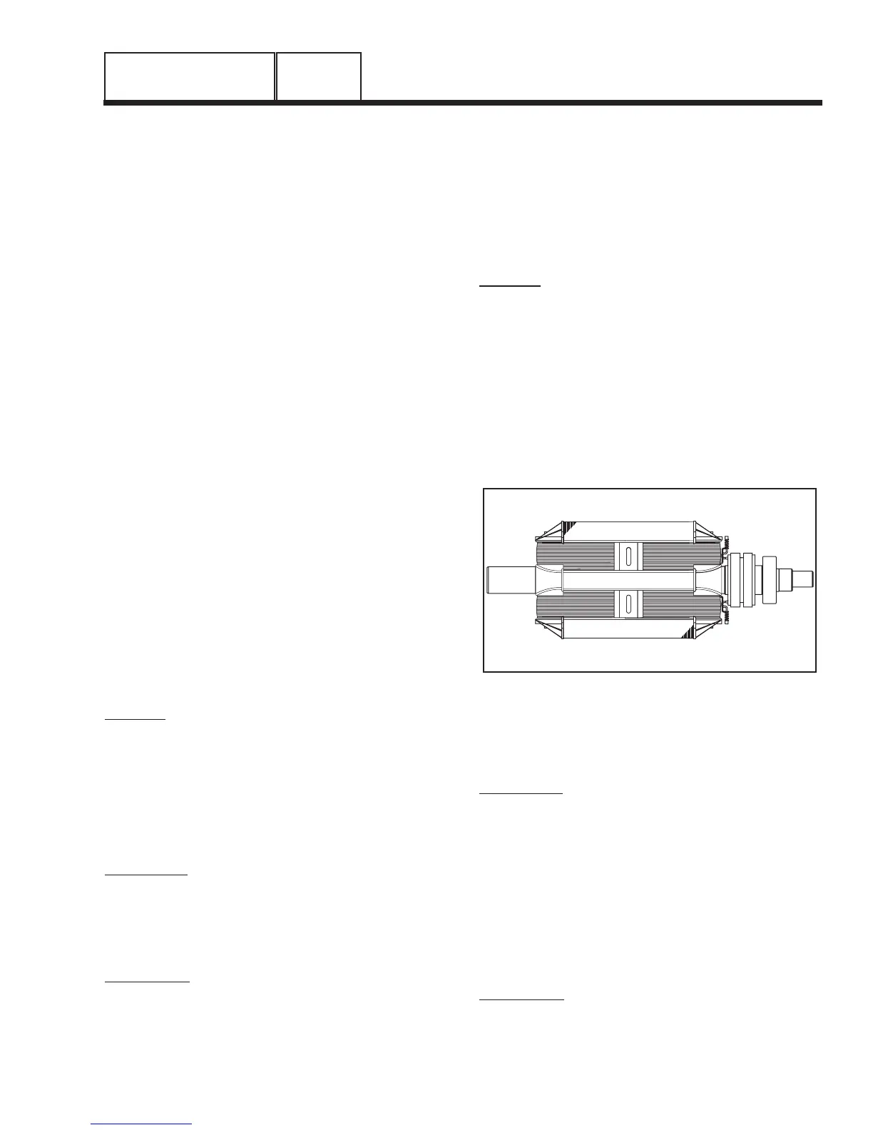
TEST 10 - TEST ROTOR ASSEMBLY
DISCUSSION:
A rotor having completely open windings will cause
loss of excitation current flow and, as a result, genera-
tor AC output voltage will drop to “residual” voltage. A
“shorted” rotor winding can result in a low voltage
condition.
PROCEDURE:
I. Disconnect the brush wires or remove the brush holder,
to prevent interaction.
2. Set a VOM to measure resistance.
3. Connect the positive (+) VOM test lead to the posi-
tive (+) rotor slip ring (nearest the rotor bearing); and
the common (-) test lead to the negative (-) slip ring.
The meter should read rotor resistance. Compare to
“Specifications,” in the front of this manual.
4. Connect the positive (+) VOM test lead to the positive (+)
slip ring and the common (-) test lead to a clean frame
ground. The meter should indicate INFINITY.
RESULTS:
1. Replace rotor assembly if it is open or shorted.
2. If rotor tests good, perform “Insulation Resistance Test”
in Section 1.4.
NOTE: Be sure to read Section 1.4, “Testing, Cleaning
and Drying”, carefully. If the rotor tests good, try per-
forming an insulation resistance test. Clean and dry the
rotor if it fails that test. Then, repeat the test. If the rotor
fails the second insulation resistance test, it should be
replaced.
Figure 7. The Rotor Assembly
TEST 11 - CHECK AC OUTPUT FREQUENCY
DISCUSSION:
The generator AC frequency is proportional to the
operating speed of the rotor. The 2-pole rotor will sup-
ply a 60 Hertz AC frequency at 3600 rpm. The unit’s
AC output voltage is proportional to the AC frequency.
For example, a unit rated 240 volts (line-to-line) will
supply that rated voltage (plus or minus 2 percent)
at a frequency of 60 Hertz. If, for any reason, the
frequency should drop to 30 Hertz, the line-to-line
voltage will drop to a matching voltage of 120 volts
AC. Thus, if the AC voltage output is high or low and
the AC frequency is correspondingly high or low, the
engine speed governor may require adjustment.
PROCEDURE:
1. Connect an accurate AC frequency meter across the
Wires 11 and 44 terminals of the generator main line
circuit breaker (see Figure 1, Section 2.4).
PART 2
Page 45