PART 4
Page 80
DC CONTROL
SECTION 4.1
DESCRIPTION AND COMPONENTS
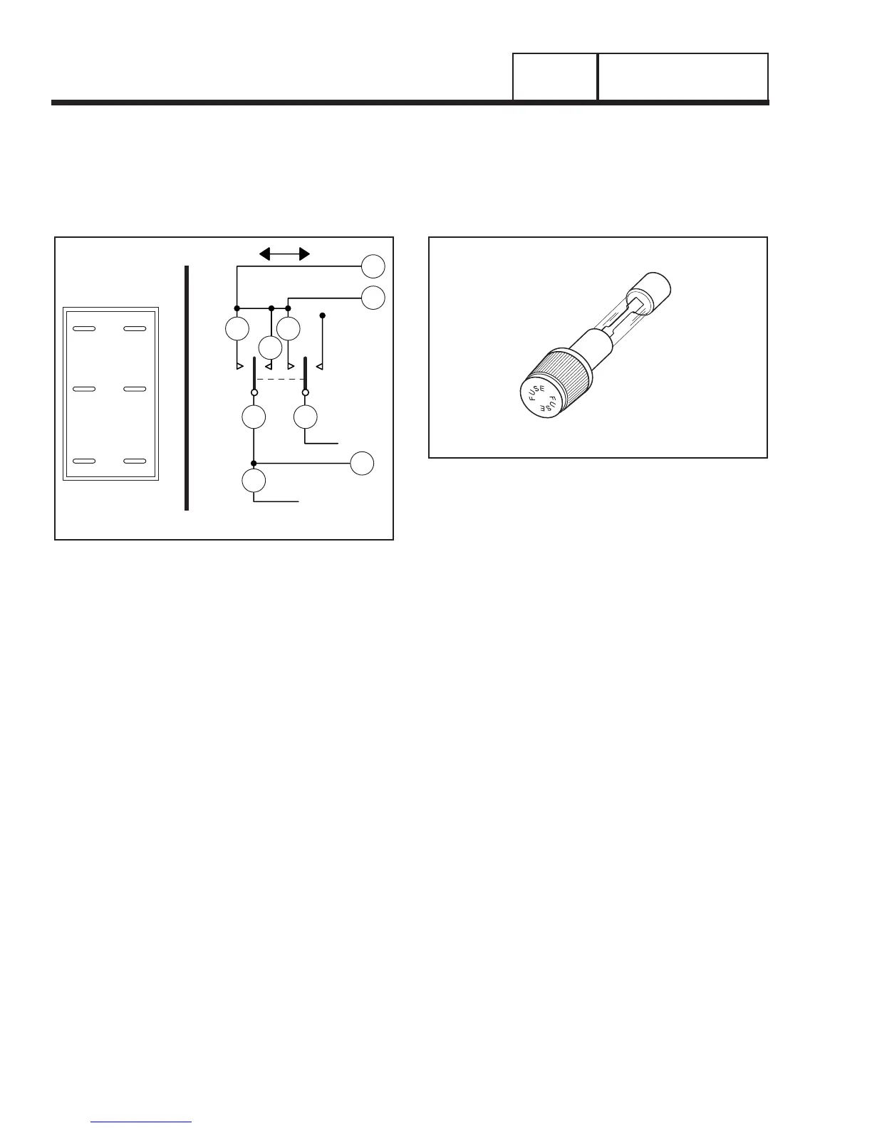
AUTO-OFF-MANUAL SWITCH
This 3-position switch permits the operator to (a)
select fully automatic operation, (b) start the genera-
tor manually, or (c) stop the engine and prevent auto-
matic startup. Switch terminals are shown pictorially
and schematically in Figure 6, below.
SW1
SCHEMATIC
MANUAL AUTO
SW1
15A
15A
194
194
194
2
5
6
43
1
1
2
3
4
5
6
15 239
15
15
Figure 6. The AUTO-OFF-MANUAL Switch
15 AMP FUSE
This fuse protects the circuit board against excessive
current. If the fuse has blown, engine cranking and
operation will not be possible. Should fuse replace-
ment become necessary, use only an identical 15-
amp replacement fuse.
Figure 7. 15 Amp Fuse