PART 2
2. Start the engine, let it stabilize and warm up at no-load.
3. When engine has stabilized, read the frequency meter.
The no-load frequency for single cylinder units should
be about 62-63 Hertz. For V-Twin units, the no-load fre-
quency should be about 57.5-59.5 Hertz.
RESULTS:
1. If the AC frequency is high or low, go on to Test 12 for
single cylinder units, or Test 12A for V-Twin units.
2. If frequency is good, but voltage is high or low, go to Test
13.
3. If frequency and voltage are both good, tests may be
discontinued.
TEST 12 - CHECK AND ADJUST ENGINE
GOVERNOR (SINGLE CYLINDER UNITS)
DISCUSSION:
The generator AC frequency output is directly pro-
portional to the speed of the rotor. A two-pole rotor
(having a single north and a single south magnetic
pole) will produce an AC frequency of 60 hertz at
3600 RPM.
The generator is equipped with a “voltage over fre-
quency” type AC voltage regulator. The units AC
output voltage is generally proportional to AC fre-
quency. A low or high governor speed will result in a
correspondingly low or high AC frequency and voltage
output. The governed speed must be adjusted before
any attempt to adjust the voltage regulator is made.
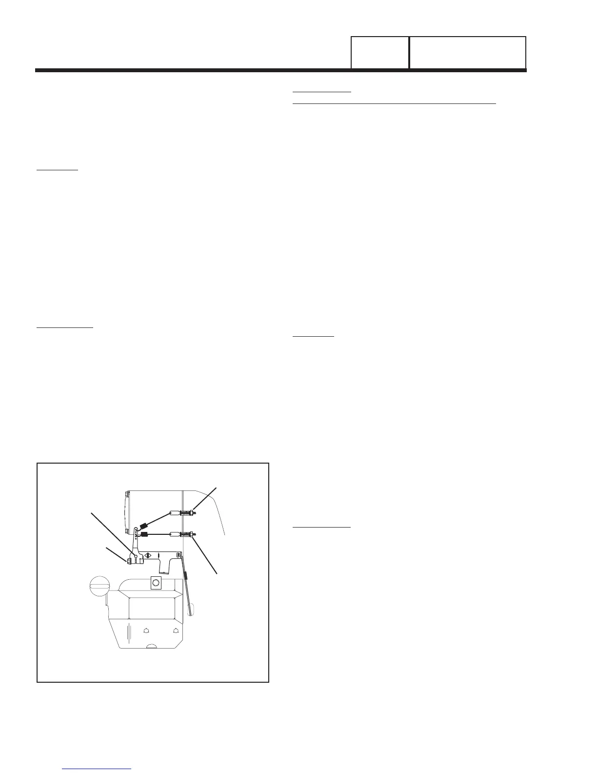
GOVERNOR
SHAFT
PRIMARY
ADJUST
SCREW
GOVERNOR
CLAMP
BOLT
SECONDARY
ADJUST SCREW
(7KW UNITS WITH DUAL GOVERNOR SPRINGS)
Figure 8. Engine Governor Adjustment Single
Cylinder Engines
PROCEDURE
(7 KW UNITS WITH DUAL GOVERNOR SPRINGS):
1. Loosen the governor clamp bolt (Figure 8).
2. Hold the governor lever at its wide open throttle position,
and rotate the governor shaft clockwise as far as it will
go. Then, tighten the governor lever clamp bolt to 70
inch-pounds (8 N-m).
3. Start the generator; let it stabilize and warm up at no-
load.
4. Connect a frequency meter across the generators AC
output leads.
5. Turn the primary adjust screw to obtain a frequency
reading of 61.5 Hz. Turn the secondary adjust screw to
obtain a frequency reading of 62.5 Hz.
6. When frequency is correct at no load, check the AC volt-
age reading. If voltage is incorrect, the voltage regulator
may require adjustment.
RESULTS:
1. If, after adjusting the engine governor, frequency and
voltage are good, tests may be discontinued.
2. If frequency is now good, but voltage is high or low, go to
Test 13.
3. If engine was overspeeding, check linkage and throttle
for binding. If no governor response is indicated refer to
engine service manual.
4. If engine appears to run rough and results in low fre-
quency, proceed to Problem 11, Section 4.3.
TEST 12A - CHECK STEPPER MOTOR
CONTROL (V-TWIN ENGINE UNITS)
PROCEDURE:
1. Remove air cleaner cover to access stepper motor.
2. Physically grab the throttle and verify the stepper motor,
linkage and throttle do not bind in any way, if any bind-
ing is felt repair or replace components as needed.
Some resistance should be felt as the stepper motor
moves through it's travel.
3. Physically move the throttle to the closed position by
pulling the stepper motor arm towards the idle stop.
See Figures 9 and 10 (for 10 kW units) or Figure 11 (for
13/16 kW Units).
a.Place the AUTO-OFF-MANUAL switch (SW1)
to MANUAL and watch for stepper motor move-
ment. It should move to the wide open position
during cranking. Once the unit starts the stepper
motor should move the throttle to a position to
maintain 57.5-59.5 Hertz.
Page 46
AC GENERATORS
SECTION 2.4
DIAGNOSTIC TESTS



 To Next Page