Do you have a question about the GW Instek SFG-2000 Series and is the answer not in the manual?
Explains warning and caution symbols used in the manual and on the device.
Provides essential guidelines for safe operation, power supply, fuse, cleaning, and environment.
Explains the Direct Digital Synthesis (DDS) technology and its advantages over traditional methods.
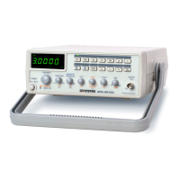
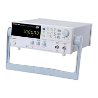
Lists SFG-2000/2100 series models and their key performance and feature specifications.
Details the function of each control, display, and connector on the front panel.
Explains the rear panel connectors for power input, external modulation, and AC voltage selection.
Guides users through setting up the tilt stand, powering on, and performing initial checks.
Lists shortcuts for performing common operations, including waveform generation and mode settings.
Instructions on how to select the desired output waveform (Sine, Square, or Triangle).
Guide on entering and editing the output frequency for the selected waveform.
Steps to enter and edit the duty cycle for square waveform output.
Instructions for setting and attenuating the output amplitude of the waveform.
Procedures for activating, adjusting, and understanding limitations of the DC offset function.
How to select between TTL and CMOS output types for digital signals.
Instructions for setting the output frequency for TTL/CMOS signals.
Guide to entering and editing the duty cycle for square wave TTL/CMOS output.
How to adjust the amplitude for CMOS output signals.
Steps to activate the sweep function for frequency response measurements.
Instructions on selecting between logarithmic and linear sweep modes.
Guide on setting the sweep time for the frequency sweep operation.
How to set the frequency span (ratio) for the sweep function.
Steps to activate and set up Amplitude Modulation.
How to adjust the modulation depth for Amplitude Modulation.
Instructions for using an external signal source for Amplitude Modulation.
Steps to activate and set up Frequency Modulation.
How to adjust the frequency deviation for Frequency Modulation.
Instructions for using an external signal source for Frequency Modulation.
Steps to connect a signal and activate the frequency counter function.
How to set the gate time to adjust update rate and resolution for the counter.
Procedures for saving the current instrument settings to memory.
Procedures for recalling previously saved instrument settings from memory.
How to restore the instrument to its factory default configuration.
Demonstrates using the SFG as a reference signal for Phase-Locked-Loop systems.
Illustrates using the SFG as a signal source for testing and troubleshooting circuits.
Shows how to test transistor DC bias characteristics using the SFG and oscilloscope.
Procedure to check amplifier overload distortion using triangle wave output.
Procedure to check amplifier transient response using square wave output.
Using SFG's TTL/CMOS output to test digital circuits and observe timing.
Procedure for testing impedance matching network frequency characteristics.
Testing audio speaker frequency response and recording voltage readings.
Using the sweep feature to test the frequency response of audio speakers.
Addresses common user inquiries regarding power, modes, accuracy, and error messages.
Details error messages related to frequency range violations for different waveforms.
Details error messages related to duty cycle settings and ranges.
Covers main output functions, amplitude, impedance, attenuator, DC offset, and duty cycle.
Details waveform frequency ranges for SFG models and triangle waveform limits.
Specifies characteristics like linearity, symmetry, rise/fall time, and CMOS output levels.
Lists specifications for Sweep Rate, Sweep Time, AM/FM depth, deviation, and carrier BW.
Includes counter accuracy, input impedance, general operation environment, and accessories.
Lists EMC standards and requirements the product complies with.
Details compliance with Low Voltage Directives and safety requirements.
| Square Wave Rise/Fall Time | < 30ns |
|---|---|
| Output Waveforms | Sine, Square, Triangle, Ramp, Pulse |
| Output Voltage | 10 Vpp (into 50Ω load) |
| Output Impedance | 50Ω |
| TTL Output Level | > 3V |
| VCF Input Impedance | 10kΩ |
| Power Source | AC 100V / 120V / 220V / 240V ±10%, 50/60Hz |
| Dimensions | 280mm |
| Modulation Types | AM/FM/FSK (SFG-2105 only) |
| Sine Wave Distortion | <1% (20Hz to 200kHz) |