3-4
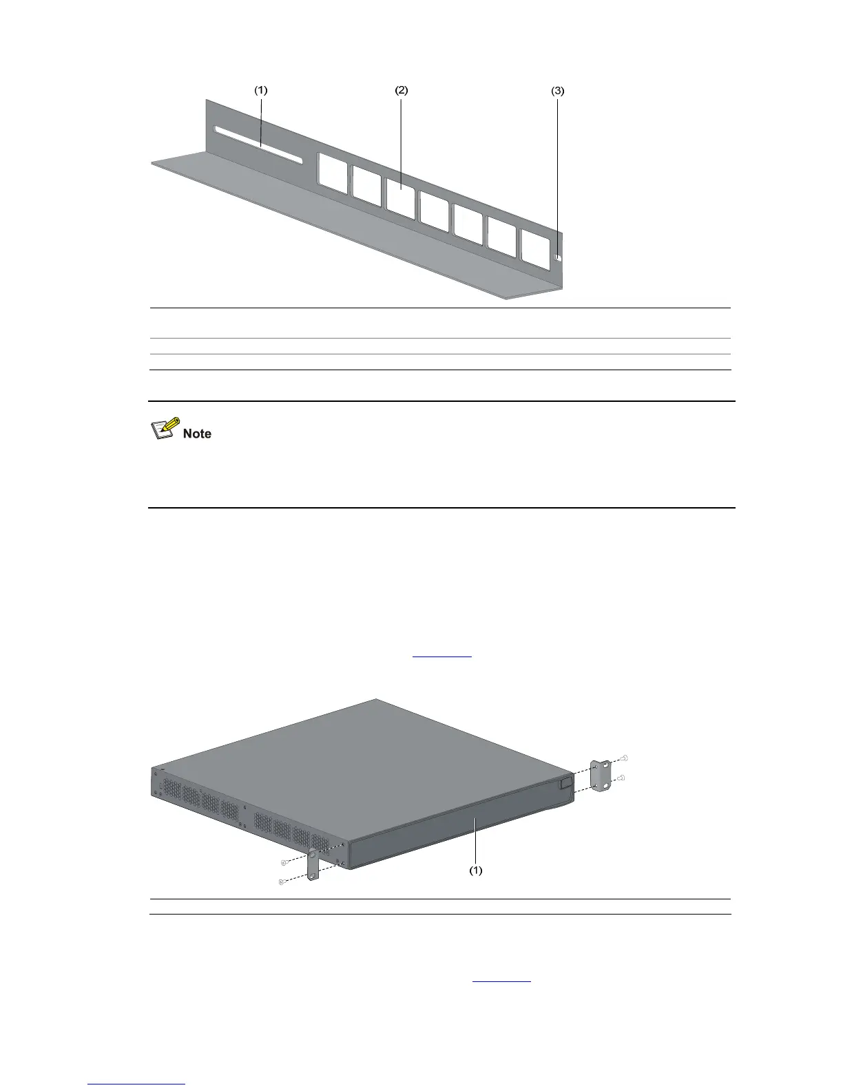
Figure 3-3 Appearance of a guide rail
(1) Slotted hole 1: Used to fix the guide rail to the rear bracket. You can adjust the screw hole position
according to the position of the switch.
(2) Cooling hole: Used for heat dissipation between switch and cabinet
(3) Slotted hole 2: Used to fix the guide rail to the front bracket
Guide rails purchased from H3C apply only to standard cabinets 1,000 mm (39.4 in.) deep. Use other
supports to substitute for guide rails in the case of other cabinet depths.
Use front mounting ears to install a switch
Follow these steps to mount a switch into a 19-inch standard cabinet:
1) Wear an ESD-preventive wrist strap to check the grounding and stability of the cabinet.
2) Take out the screws which are packed together with the front mounting ears, and fix one end of
mounting ears to the switch, as shown in
Figure 3-4.
Figure 3-4 Fix front mounting ears (1)
(1) Front panel
3) Place the switch horizontally in a proper position, and fix the other end of mounting ears to the front
brackets with screws and captive nuts, as shown in
Figure 3-5.

 Loading...


