45
Figure 57 Appearance of an LC connector
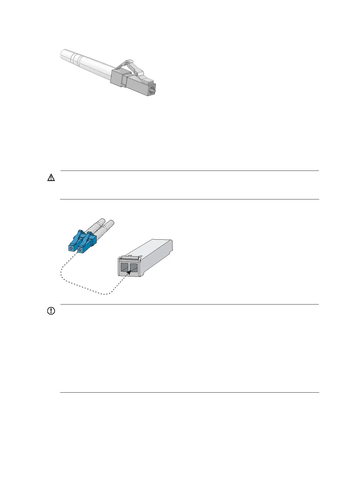
Follow these steps to connect your switch to the network through optical fibers:
Step1 Remove the dust cover of the optical fiber connector, and clean the end of the optical fiber.
Step2 Take off the dust plug of the SFP transceiver module, plug one end of the optical fiber into the transceiver
module in the switch, and plug the other end into the transceiver module in the access device, as shown
in Figure 58.
Step3 Check that the LEDs of the optical interfaces are normal.
WARNING!
To avoid injury to your eyes, do not stare at the optical interfaces and optical fiber connectors when
connecting optical fibers.
Figure 58 Use the LC optical fiber connector to connect a transceiver module
LC plug
SFP module
IMPORTANT:
• Each SFP port is a member port of a combo interface. After connectin
the switch to the network throu
h
the SFP port, you must use the combo enable fiber command to activate the SFP port.
• After connecting the switch to the network, you can use the ping or tracert command to check the
interoperability between the switch and the network. For more information, see the
H3C S3100V2
Switch Series Command References
.
• If the port status LED on the switch flashes after you connect the switch to the network, and the switch
does not respond to your commands, the switch may be sending
or receivin
broadcasts. In this case,
disconnect the switch to the network, re-configure the switch, and connect the switch to the network
again.

 Loading...


