1-5
S5500-28C-EI-DC
Front Panel
The front panel of the S5500-28C-EI-DC is the same as that of the S5500-28C-EI. For related
description, refer to
S5500-28C-EI on page 1-3.
Rear Panel
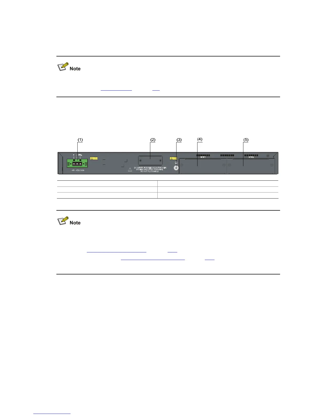
Figure 1-3 Rear panel of the S5500-28C-EI-DC Ethernet switch
(1) -48V DC power input (2) RPS power input (shipped with a protective cover)
(3) Grounding screw (4) Interface module slot 1 (MOD1)
(5) Interface module slot 2 (MOD2)
The S5500-28C-EI-DC provides two interface module slots on its rear panel. Each slot is installed with
a filler panel when the switch is shipped. You can select one or two interface modules for your switch as
needed. See
Optional Interface Modules on page 1-17 for the interface module models supported by
the S5500-EI series, and see
Installing an Interface Module on page 3-21 for the installation of interface
modules.
S5500-52C-EI
Front Panel
The S5500-52C-EI Ethernet switch provides 48 ×10/100/1000Base-T auto-sensing Ethernet ports, four
1000 Base-X SFP ports and one console port on the front panel. The last four 10/100/1000Base-T
Ethernet ports and the four SFP ports comprise four Combo ports, with one port of a Combo port
working at a time.
 Loading...


