3-13
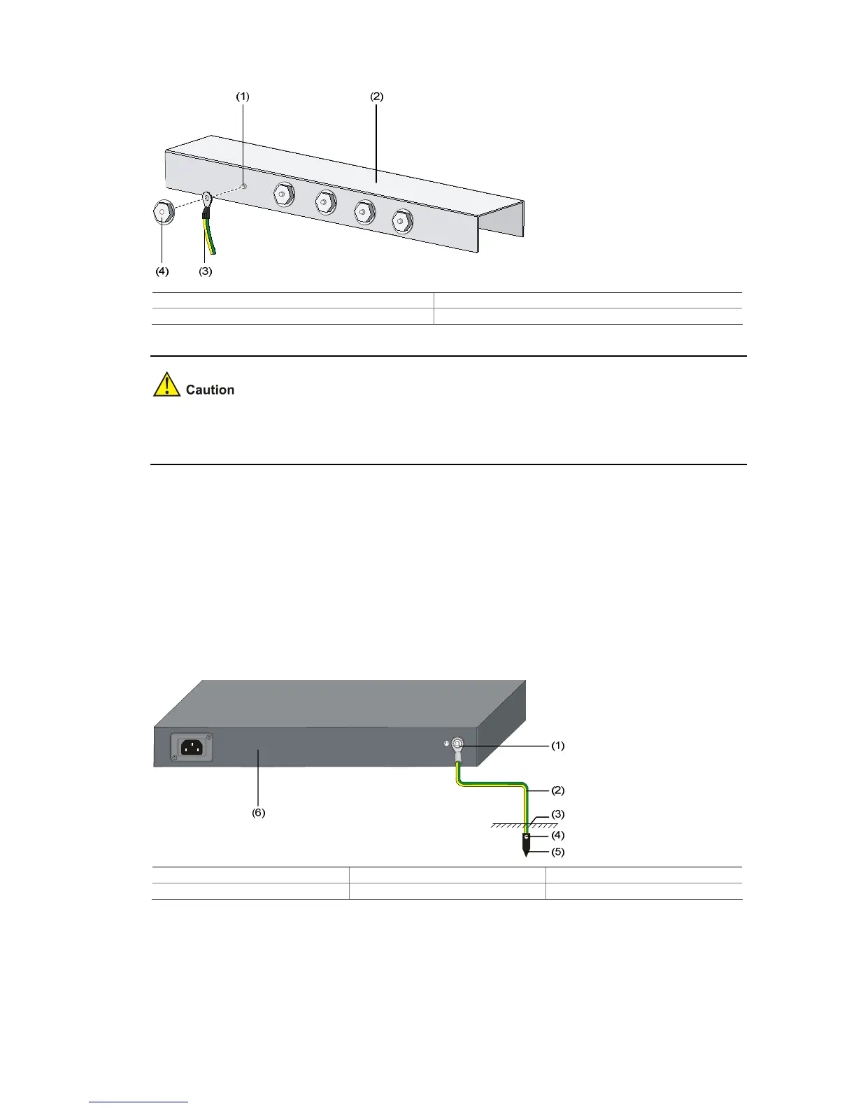
Figure 3-16 Connect the PGND cable to the grounding strip
(1) Grounding post (2) Grounding strip
(3) PGND cable (4) Hex nut
The fire main and lightning rod of a building are not suitable for grounding the switch. The ground wire of
the switch should be connected to the grounding device for the equipment room.
Where a Grounding Conductor Can be Buried
When there is no grounding strip, but an area with exposed earth is available nearby where a grounding
conductor can be buried, hammer a 0.5 m (1.64 ft.) or longer angle iron or steel tube into the earth. The
angle iron should have a dimension no less than 50 × 50 × 5 mm (1.97 × 1.97 × 0.20 in.) and the steel
tube should have a wall thickness no less than 3.5 mm (0.14 in.) and be zinc-coated. Weld the
yellow-green ground wire to the angel iron or steel tube and treat the joint for corrosion protection.
Figure 3-17 Ground the switch by burying the grounding conductor into the earth
(1) Grounding screw (2) PGND cable (3) Earth
(4) Joint (5) Grounding conductor (6) Switch rear panel
 Loading...


