1-15
Seven-Segment LED
The seven-segment LED and the system status LED together indicate the operating status of the
device. For details, refer to
Table 1-11.
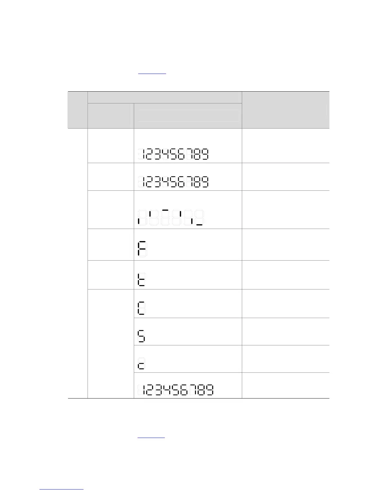
Table 1-11 Seven-segment LED description (1)
Status
LED
System status
LED
(PWR/SYS)
Seven-segment LED
Description
Flashing green
The LED displays the specific numbers
one by one.
POST running. The LED
displays the POST test ID.
Flashing red
The LED flashes the specific numbers.
POST failed. The LED flashes
the POST test ID of the failed
test.
Flashing green
A bar rotates clockwise around the
LED.
Software loading
Steady red
The LED flashes F.
Fan failure
Steady red
The LED flashes t.
Over-temperature alarm
The LED displays C.
The current switch is the
command switch in the cluster.
The LED displays S.
The current switch is a member
switch in the cluster.
The LED displays c.
The current switch is a
candidate switch in the cluster.
Unit
Steady green
The LED displays the specific numbers.
The member ID of the current
switch.
The seven-segment LED, the system status LED, and the port mode LED on the S5500-28C-PWR-EI
or S5500-52C-PWR-EI that supports PoE can display the PoE power consumption percentage of the
switch. For details, refer to
Table 1-12.
 Loading...


