3-3
Introduction to Mounting Bracket
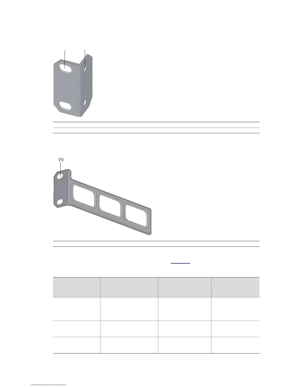
Figure 3-2 Appearance of a standard front mounting bracket
(1) (2)
(1) Screw hole used to fix the mounting bracket to the cabinet (Use one M6 screw)
(2) Screw hole used to fix the switch to the mounting bracket
Figure 3-3 Appearance of a rear mounting bracket
(1) Screw hole used to fix the mounting bracket to the cabinet (Use one M6 screw)
For the selection of front and rear mounting brackets, see
Table 3-2.
Table 3-2 Selection of mounting bracket for S5500-EI Series Ethernet switches
Model
Physical dimensions (H
× W × D)
Configuration type of
front mounting
bracket
Configuration type
of rear mounting
bracket
S5500-28C-EI
S5500-52C-EI
S5500-28C-EI-DC
43.6 × 440 × 300 mm
(1.72 × 17.32 × 11.81 in.)
Standard —
S5500-28C-PWR-EI
S5500-52C-PWR-EI
43.6 × 440 × 420 mm
(1.72 × 17.32 × 16.54 in.)
Standard Standard
S5500-28F-EI
43.6 × 440 × 360 mm
(1.72 × 17.32 × 14.17 in.)
Standard Standard
 Loading...


