1-9
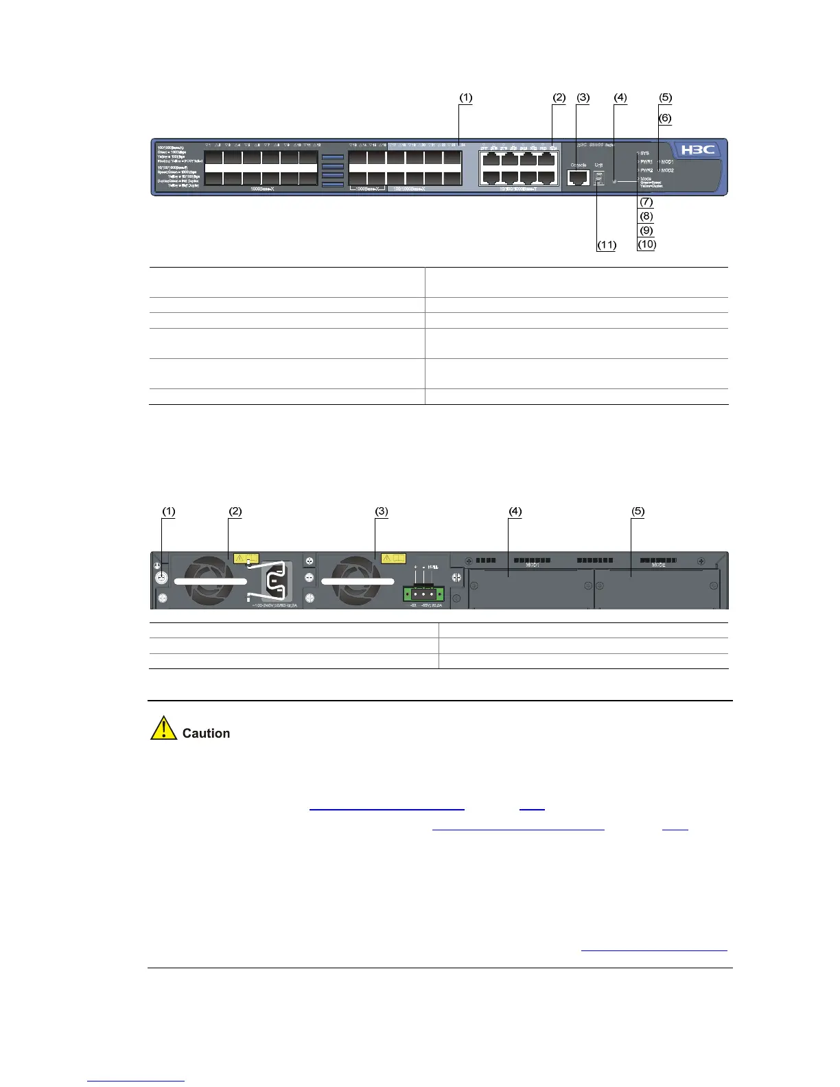
Figure 1-10 Front panel of the S5500-28F-EI Ethernet switch
(1) 100/1000Base-X SFP port status LED (2) 10/100/1000 Base-T auto-sensing Ethernet port
status LED
(3) Console port (4) Port status LED mode switching button
(5) Interface module 1 status LED (MOD1) (6) Interface module 2 status LED (MOD2)
(7) System status LED (SYS) (8) Hot swappable power module 1 status LED
(PWR1)
(9) Hot swappable power module 2 status LED
(PWR2)
(10) Port mode LED (Mode)
(11) Seven-segment LED
Rear Panel
Figure 1-11 Rear panel of the S5500-28F-EI Ethernet switch
(1) Grounding screw (2) Hot swappable power module 1
(3) Hot swappable power module 2 (4) Interface module slot 1 (MOD1)
(5) Interface module slot 2 (MOD2)
z The S5500-28F-EI provides two interface module slots on its rear panel. Each slot is installed with
a filler panel when the switch is shipped. You can select one or two interface modules for your
switch as needed. See
Optional Interface Modules on page 1-17 for the interface module models
supported by the S5500-EI series, and see
Installing an Interface Module on page 3-21 for the
installation of interface modules.
z The S5500-28F-EI provides two power module slots on its rear panel, with only a power module
RPS150-A installed in PWR1 upon device delivery while a blank panel on PWR2. You can install a
power module, which can be PSR150-A or PSR150-D, in PWR2 to serve as a backup. For details
about PSR150-A and PSR150-D, refer to H3C PSR150-A & PSR150-D Power Modules User
Manual. For details about how to install the two power modules, refer to
Installing a Power Module.
 Loading...


