18
Mounting the switch on a wall
Before drilling holes in a wall, make sure no electrical lines exist in the wall.
• Leave a minimum clearance of 10 mm (0.39 in) around the chassis for heat dissipation.
The S5120V2-SI, S5120V2-LI, S5000V3-EI, S5000V5-EI, and S3100V3-SI switch series support
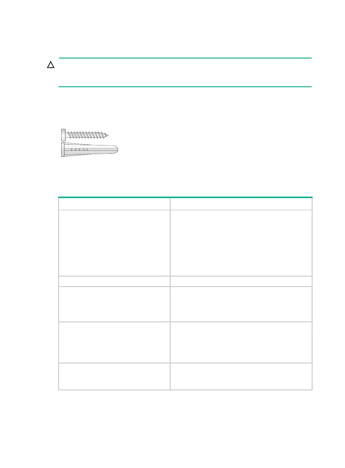
wall mounting. These switches are provided with screw anchors and screws as shown in Figure 13
for wall-mounting.
Figure 13 Screw anchor and screw
Table 9 describes the switch models that support wall mounting and installation holes distances
required for wall-mounting the switch.
Table 9 Installation hole distances for switch models that support wall mounting
Switch model Hole distance
S5120V2-10P-SI
S5120V2-10P-LI
S3100V3-10TP-SI
S5024PV5-EI-S
S5008PV5-EI with product code
LS-5008PV5-EI-H1
S5008PV5-EI-S
S5008PV5-EI-HPWR-S
170 mm (6.69 in)
S3100V3-18TP-SI 172 mm (6.77 in)
S5120V2-20P-LI
S5016PV3-EI
S5016PV5-EI
S5016PV5-EI-S
176 mm (6.93 in)
S5120V2-10P-PWR-LI
S5120V2-12TP-HPWR-LI
S3100V3-10TP-PWR-SI
S5008PV5-EI-HPWR with product code
LS-5008PV5-EI-HPWR-H1
102 mm (4.02 in)
S3100V3-20TP-PWR-SI
S5016PV5-EI-PWR-S
S5024PV5-EI-PWR-S
116 mm (4.57 in)
To mount the switch on a wall:
1. Mark two installation holes on the wall. Make sure the two holes are on the same horizontal line.
See Table 9 for the distance requirement between the two holes.

 Loading...


