43
Chassis Candidate IRF physical ports Use restrictions
bound to different IRF ports.
The ports must operate at 1 Gbps.
Other switch models
The physical ports bound to an IRF port
must operate at the same speed.
The ports must operate at 1 Gbps.
Planning the cabling scheme
Use the following cables to connect the IRF physical ports on the switches:
10/100/1000BASE-T autosensing Ethernet port—Category 5 or above twisted-pair cables.
SFP port—GE SFP fiber transceiver modules and optical fibers, GE SFP copper transceiver
modules and twisted-pair cables, or GE SFP cables. For the available models, see ports in
hardware information and specifications for the switch series.
SFP+ port—SFP+ transceiver modules and optical fibers or SFP+ cables. For the available
models, see ports in hardware information and specifications for the switch series.
If the IRF member switches are far away from one another, use transceiver modules and optical
fibers. If the IRF member switches are all in one equipment room, use twisted pair cables or
SFP/SFP+ cables.
The following subsections describe several H3C recommended IRF connection schemes by using
SFP cables and SFP transceiver modules and fibers. All these schemes use a ring topology.
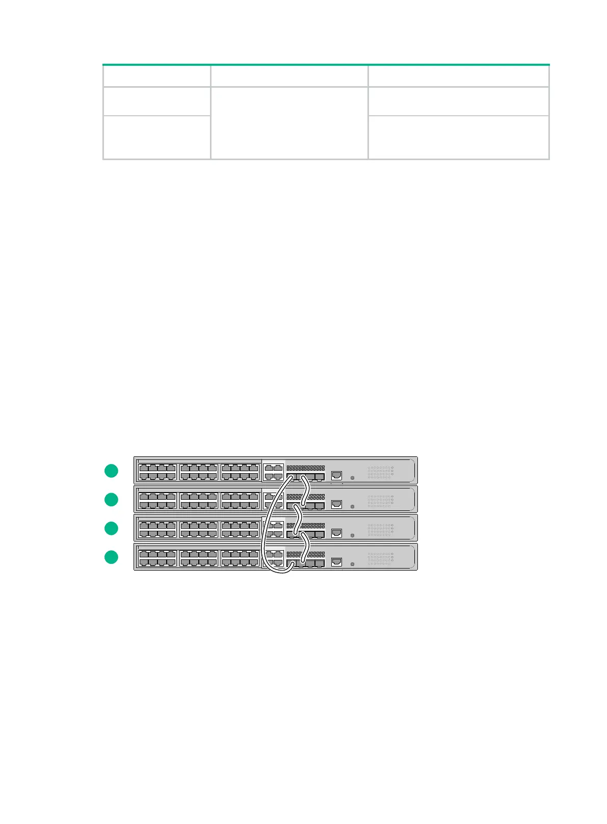
Connecting the IRF member switches in one rack
Connect the IRF member switches (4 switches in this example) in a rack as shown in Figure 40. The
switches in the ring topology (see Figure 41) are in the same order as connected in the rack.
Figure 40 Connecting the switches in one rack

 Loading...


