22
In cold areas, bury the grounding conductor below the frozen soil layer. In areas with thin soil or rocky
gravel, determine the depth for burying the grounding conductor based on the actual condition.
If zinc-coated steel is used, the following dimensions requirements must be met:
Angle iron—A minimum of 50 × 50 × 5 mm (1.97 × 1.97 × 0.20 in).
Steel tube—A minimum of 3.5 mm (0.14 in) in thickness.
Flat steel—A minimum of 40 × 4 mm (1.57 × 0.16 in).
Round steel—A minimum of 10 mm (0.39 in).
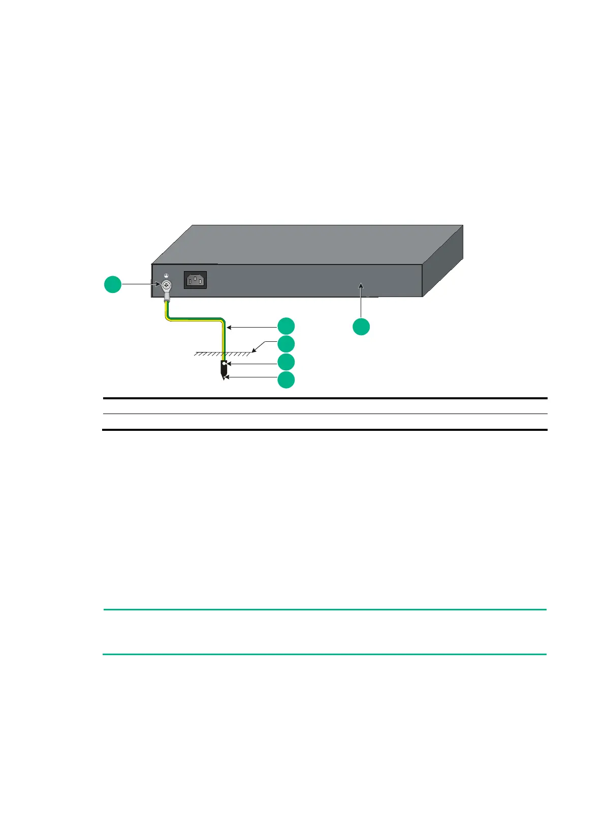
Weld the yellow-green grounding cable to the angel iron or steel tube and treat the joint for corrosion
protection.
Figure 19 Grounding the switch by burying the grounding conductor into the earth ground
Grounding the switch by using the PE wire of the AC power
cord
If the installation site has no grounding strips or earth ground, ground an AC-powered switch through
the PE wire of the power cord. Make sure the following requirements are met:
The power cord has a PE wire.
The ground contact in the power outlet is securely connected to the ground in the power
distribution room or on the AC transformer side.
The power cord is securely connected to the power outlet. If the ground contact in the power
outlet is not connected to the ground, report the problem and reconstruct the grounding system.
To guarantee the grounding effect, use the grounding cable provided with the switch to connect to
the grounding strip in the equipment room.
Verifying the connection after grounding the switch
If you ground the switch with a grounding strip:
a. Use a multimeter to measure the resistance between the switch grounding terminal and
grounding point, and make sure the resistance is less than 0.1Ω.

 Loading...


