23
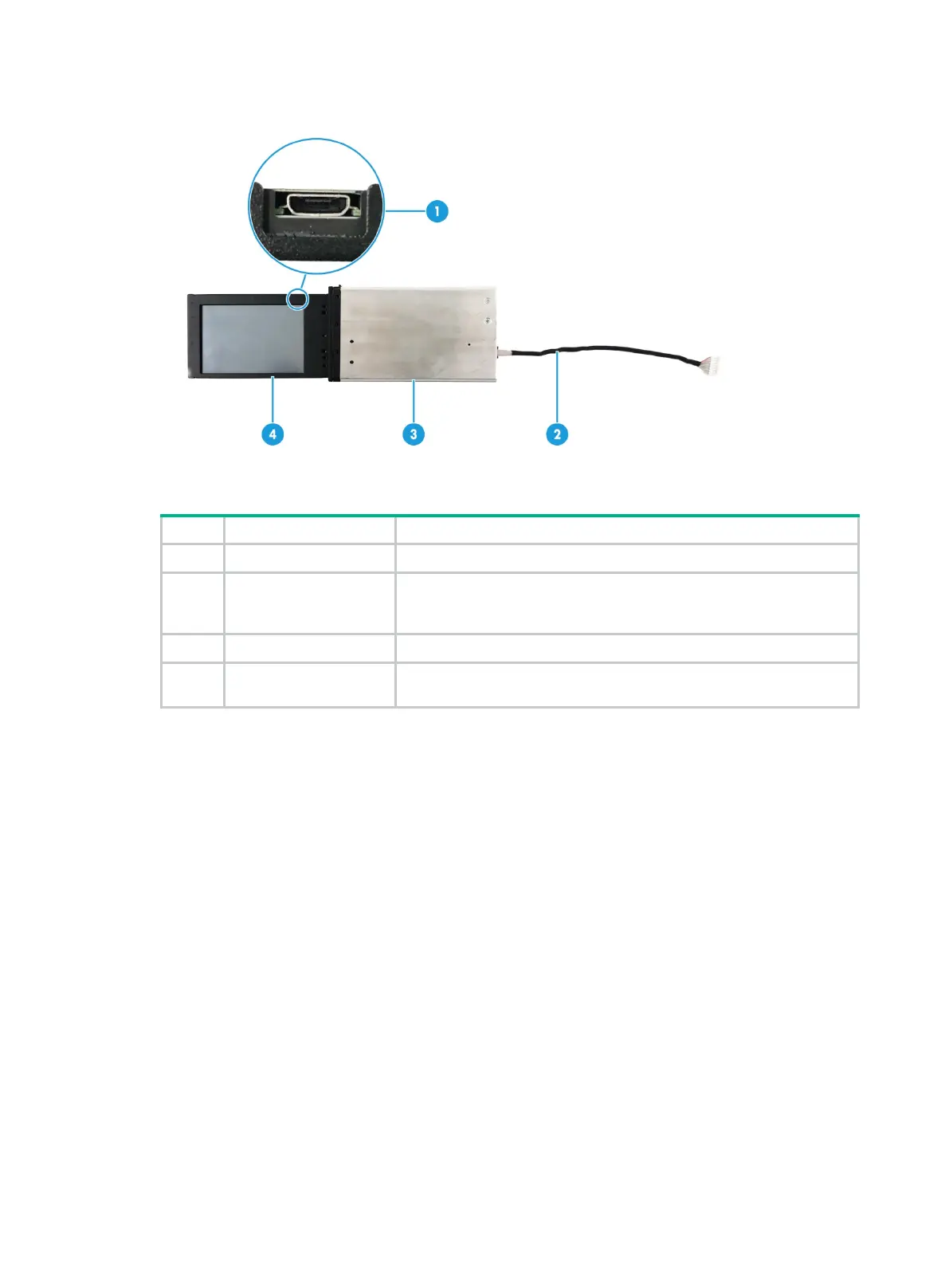
Figure 25 LCD smart management module
Table 13 LCD smart management module description
1 Mini-USB connector Used for upgrading the firmware of the LCD module.
2 LCD module cable
Connects the LCD module to the system board of the server. For
information about the LCD smart management module connector on
the system board, see "System board."
Protects and secures the LCD screen.
4 LCD screen
Displays basic server information,
operating status, and fault
information.
Fan modules
The server supports eight hot swappable fan modules. The server supports N+1 fan module
redundancy. Figure 26 shows the layout of the fan modules in the chassis.
The server can adjust the fan rotation speed based on the server temperature to provide optimal
performance with balanced ventilation and noise.

 Loading...


