Section 1
Page 19
54400_install.fm Sample Conditioning
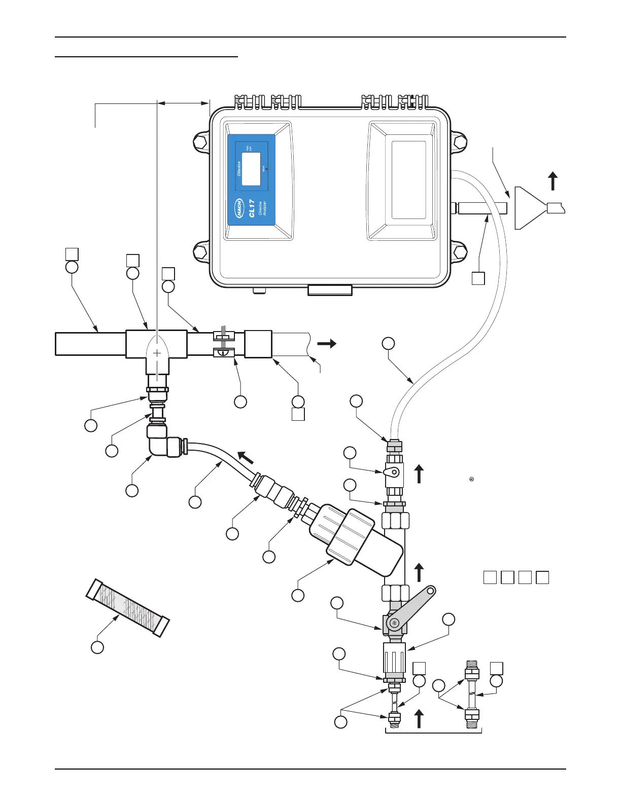
Figure 6 Sample Conditioning Kit
Notes: Unless otherwise specified.
6. Cut tube ends square with a sharp knife or cutter.
2 Use PVC pipe cement to assemble.
3 This is the “Low Flow” option.
4 This is the “High Flow” option.
5 1/2 inch drain tube must have an air-break. (Must be supplied by the customer.)
5
2
3
4
2
2
2
The filter element
is factory installed.
A spare filter is
provided in the
Maintenance Kit.
12
6
13
Clear 1 inch pipe to observe bypass flow.
2
1
Unfiltered Sample Bypass
Customer Supplied PVC pipe
as required to run to drain location.
194
7
16
18
14
Mount in convenient location.
Close to the instrument
and easily accessible.
Remove the hex-plug before installation.
5
11
17
10
172 inches long max
9
4
3
7
8
16
17
14
OR
Install the Sample Flow Regulator
(Constant Head Device)
24 inches above the instrument.
Drain
Air Gap
1. Apply Item 15 Teflon thread tape to pipe threads.
EXIT ENTER
Chlorine
mg/L
µg/L
Alarm
MENU
 Loading...