68
Inputs/Outputs Menu
Analog outputs
There are three analog outputs per channel. These outputs are configurable in terms of function, content,
and behavior through the instrument menus. Analog outputs are used to output a voltage or a current
which is a function (e.g. a linear characteristic) of a measurement: AOut = f (M). The analog outputs can
be typically connected to a PLC. Knowing the function (f), the PLC can compute the value of the
measurement.
Two types of instrument hardware are available:
• measurement board with current output (I = 0-20 mA or 4-20 mA).
• measurement board with voltage output (U = 0-5 V).
Instrument
configuration
• Select analog output range of current:
4-20 mA or 0-20 mA
• The 4-20 mA range (recommended) allows for an extended event
indication mode that can be selected and configured (default = standard
mode)
Note: Features of the instrument with a voltage analog output are similar to
the 0-20 mA features.
For some events (sensor out, purge failure, etc.) the actual measurement is
not significant, but the PLC needs to know how the analog output behaves
in these cases. Two "Event indication modes" are available:
• Standard mode (default)
• Extended mode
Standard event
indication
Refer to Table 1 Standard event indication below.
Extended event
indication
The "Extended event indication" mode is only available when the 4-20 mA
output is selected. In this mode, the range between 0 mA and 4 mA is used
to indicate selected events. The events are defined using the channel
configuration option. Refer to Channel configuration on page 69.
Note: The extended mode is not available for the voltage output versions of
the instrument.
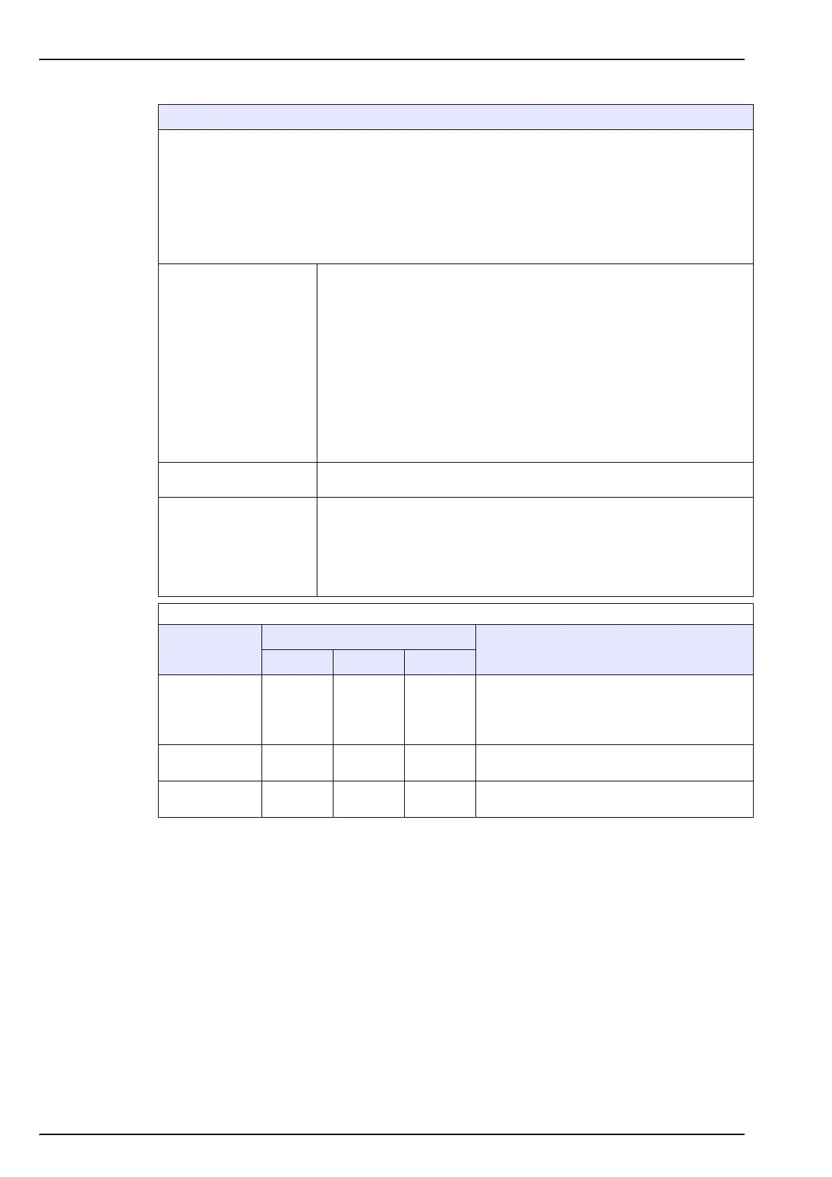
Table 1 Standard event indication
Analog output
Event output range
Event
0-20 mA 4-20 mA 0/5 V
Gas
concentration
20 mA 20 mA 5 V
• Channel out
• Sensor out
• Thermal cut-off
• Interfering gas error
Temperature 20 mA 20 mA 5 V
• Channel out
• Sensor out
External
pressure
20 mA 20 mA 5 V
• Channel out
• External pressure sensor out
 Loading...