14
Installation
3.2 Electrical Installation
DANGER
The instrument must be installed
by qualified technical personnel
for adherence to all applicable
electrical codes. The 1720E/sc100
product configuration is not
intended for installation in
hazardous locations.
High-voltage wiring for the controller is conducted behind the high voltage
barrier in the controller enclosure. The barrier must remain in place unless a
qualified installation technician is installing wiring for power, alarms, or relays.
See Figure 12 for barrier removal information.
3.2.1 Installation in Conduit
In hard-wired electrical applications, the power and safety ground service drops
for the instrument must be 18 to 12 AWG. See Figure 13 on page 15 for strain
relief and conduit opening sealing plug information. See section 3.2.3 on page 15
for wiring information.
3.2.2 Installation Using a Power Cord
DANGER
Use of power cords is not
permitted in hazardous locations.
Where permitted by local electrical codes, a sealing-type strain relief to
maintain the NEMA 4X/IP66 environmental rating and a power cord less than
3 meters (10 feet) in length with three 18-gauge conductors (including a safety
ground wire) can be used, see Replacement Parts and Accessories on page 55.
See Figure 13 on page 15 for strain relief and conduit opening sealing plug
assembly. See section 3.2.3 on page 15 for wiring information.
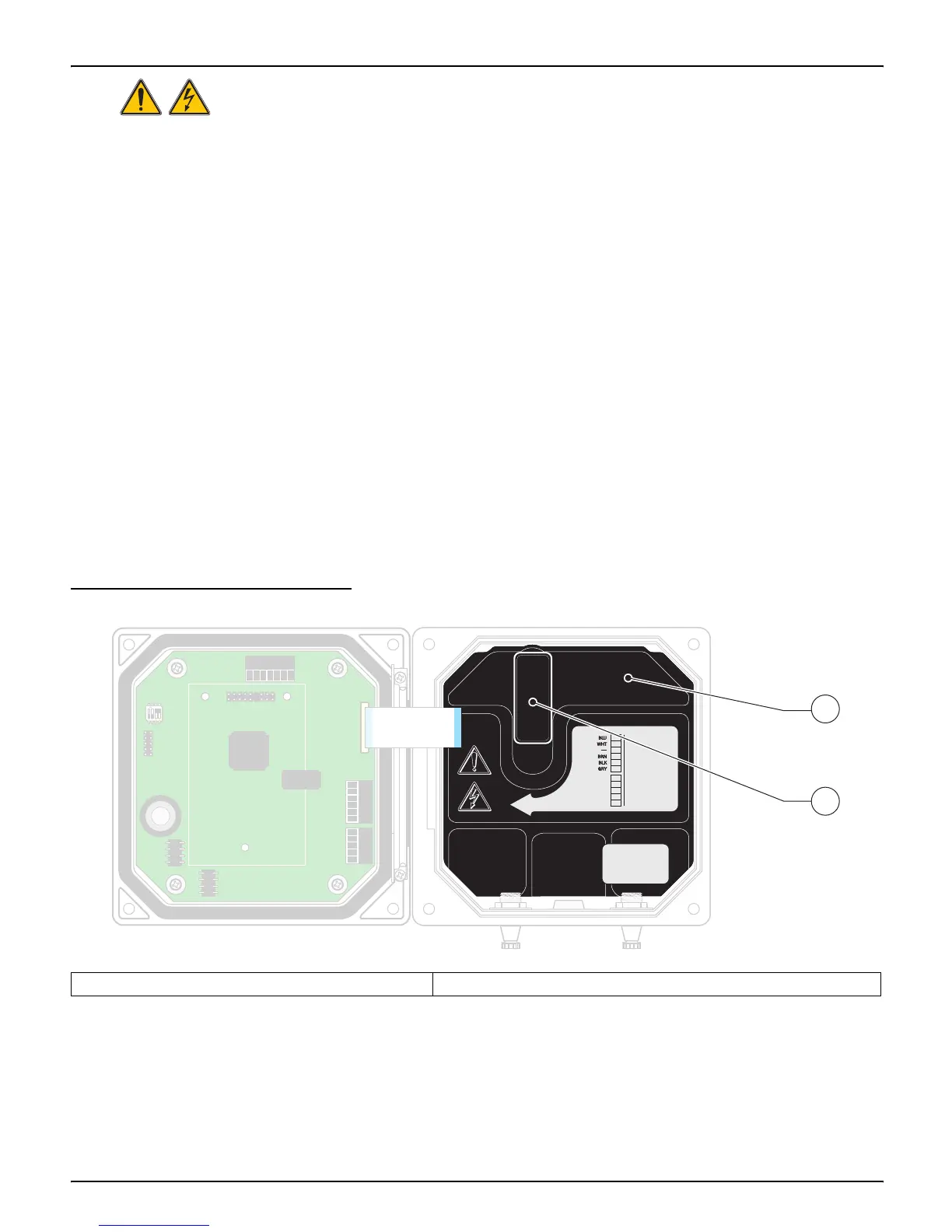
Figure 12 Removing Voltage Barrier
1. High voltage barrier 2. Unsnap the barrier latch then pull out to remove the barrier.
1
1
+ DATA
+ OUT 2
– DATA
– OUT 2
SERVICE REQUEST
SHIELD/CHASSIS GND
+ V
+ OUT 1
GND
– OUT 1
2
2
3
3
4
4
5
5
6
PROBES
ANALOG OUTPUTS
PCB
CONNECTOR
FIELD WIRING
INSULATION MUST
BE RATED TO
80° C MINIMUM
FIELD WIRING
INSULATION MUST
BE RATED TO
80° C MINIMUM
J1
J2
J4
NETWORK
INTERFACE
CARD
J3
J5
J6
U5
U9
S1
1
1
+ DATA+ DATA
+ OUT 2+ OUT 2
– DATA
– OUT 2
SERVICE REQUEST
SHIELD/CHASSIS GND
+ V+ V
+ OUT 1+ OUT 1
GND
– OUT 1
2
2
3
3
4
4
5
5
6
PROBES
ANALOG OUTPUTS
PCB
CONNECTOR
PCB
CONNECTOR
FIELD WIRING
INSULATION MUST
BE RATED TO
80° C MINIMUM
FIELD WIRING
INSULATION MUST
BE RATED TO
80° C MINIMUM
J1
J2
J4
NETWORK
INTERFACE
CARD
J3
J5
J6
U5
U9
S1
2
1

 Loading...