Installation
25
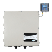
Figure 24 Sampling Techniques
3.8 Sample Connections
Sample inlet and drain connections are made on the turbidimeter body. The
sample inlet fitting installed in the body is a ¼-inch NPT
x ¼-inch compression
fitting. One additional fitting supplied with the instrument is a ½-inch NPT-to-hose
fitting for use with ½-inch ID flexible plastic tubing on the drain.
Note: For samples with high solids
content (high turbidity), operate at
the highest flow rate possible. For
samples with low solids content (low
expected turbidity), operate at a low
flow rate (200–300 mL/min).
The required flow rate is 200 to 750 mL/minute (4.0 to 11.9 gal/hour). Flow rate
into the turbidimeter may be controlled with a flow restriction device on the inlet
line. Flow rates below 200 mL/min will reduce response time and cause
inaccurate readings. Flow rates above 750 mL/min will cause the turbidimeter to
overflow, indicating the flow rate is too high.
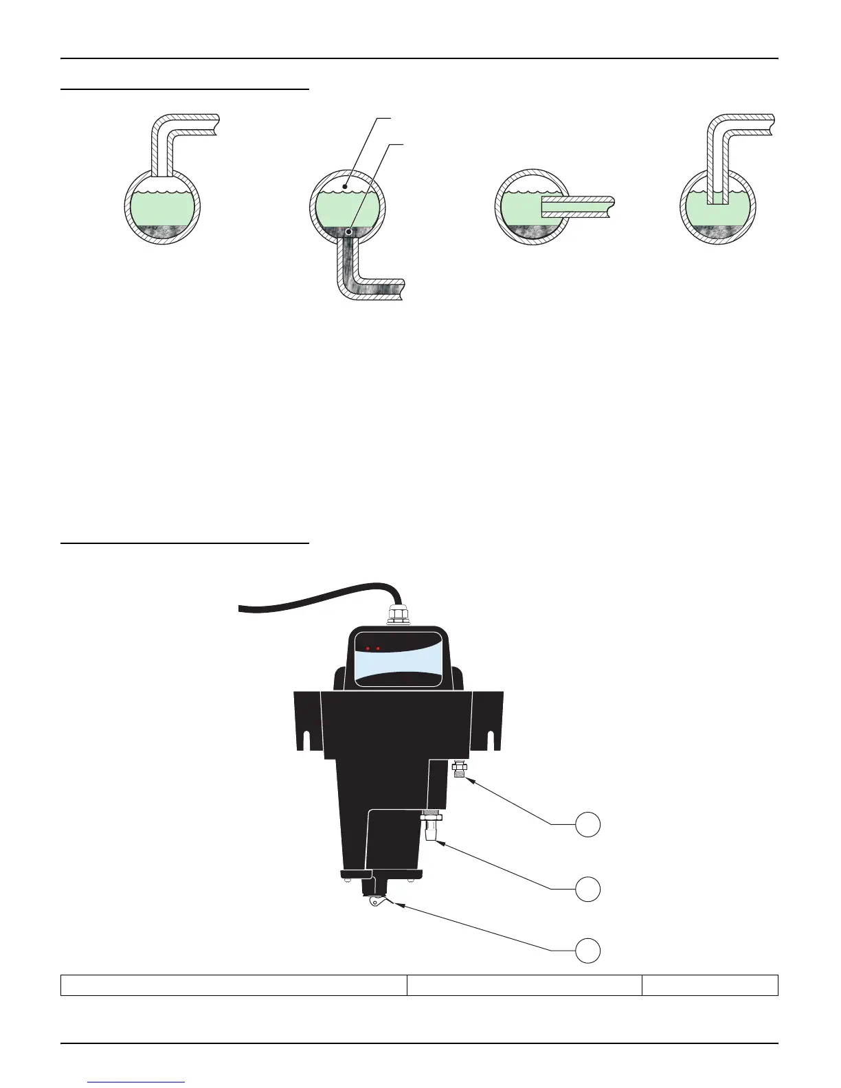
Figure 25 Sample Connections
Poor
Sediment (Typical)
Air (Typical)
Poor
Good Best
1. Sample Inlet, ¼-28 NPT x ¼-inch Compression fitting 2. Drain, ½-inch NPT fitting 3. Service Drain
POWER
STATUS
1
2
3

 Loading...