8
Section 3 Installation
DANGER
Only qualified personnel should conduct the installation tasks described in
this section of the manual. The 1720E/sc100 product configuration is not
intended for installation in hazardous locations.
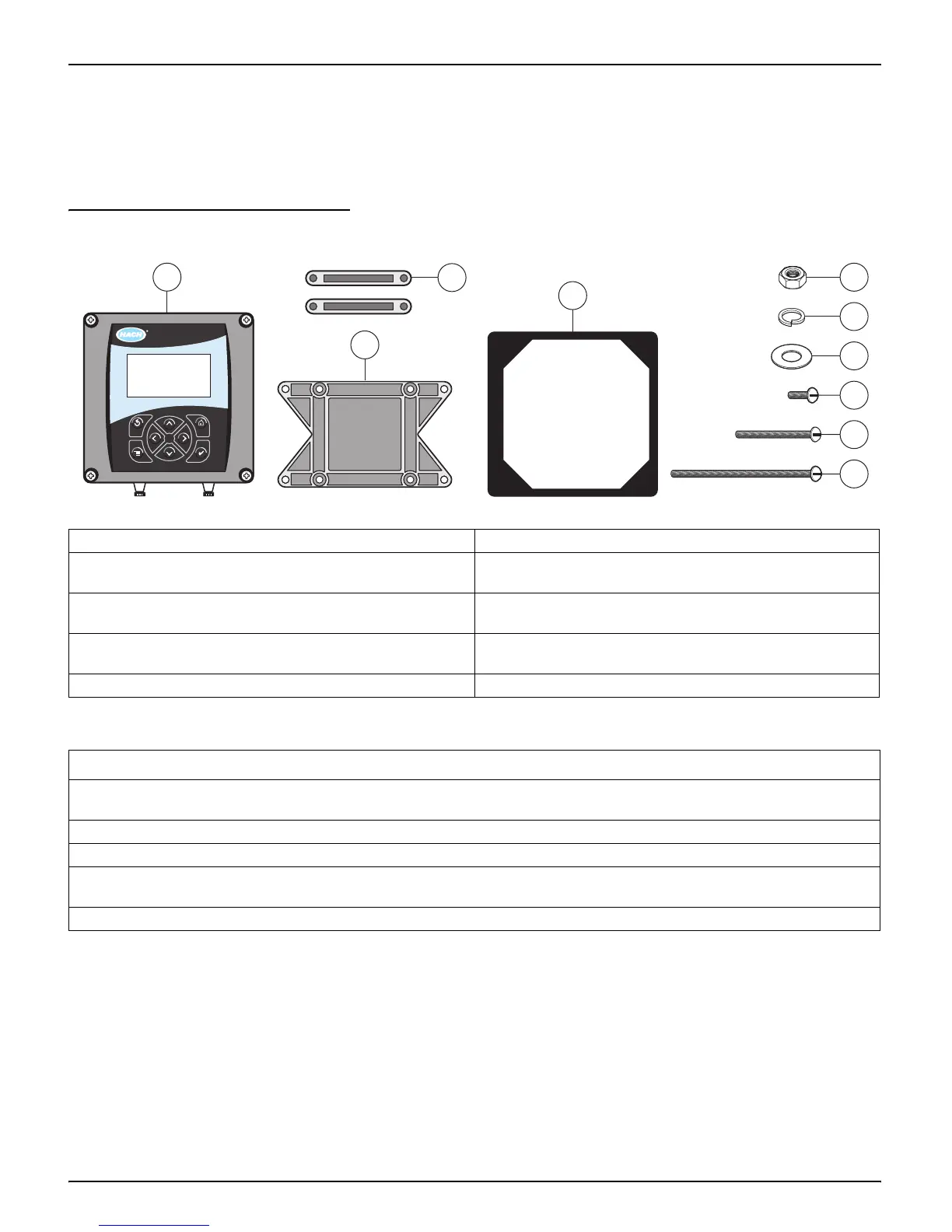
Figure 2 Controller Mounting Components
3.1 Mechanical Installation
Install in an environment that is protected from corrosive fluids. The sensor is
adversely affected by ClO
2
. Install the sensor in an area well ventilated from any
corrosive liquids or gasses.
1. Controller 6. Lock washer, ¼-inch I.D. (4), Cat. No. 8H1336
2. Mounting foot for panel mounting (2),
Cat. No. 1000B4F3222
7. Flat washer, ¼-inch I.D. (4), Cat. No. 8H1346
3. Bracket for panel and pipe mounting,
Cat. No. 1000C4F3217-101
8. Pan head screws (4), M6 x 1.0 x 20 mm, Cat. No. 58674-00
4. Gasket for panel mounting, rubber,
Cat. No. 1000A4F3249-101
9. Pan head screws (4), M6 x 1.0 x 100 mm, Cat. No. 5867500
5. Hex nut, M6 (4), Cat. No. 5867300 10. Pan head screws (4), M6 x 1.0 x 150 mm, Cat. No. 5867600
Table 3 Customer-supplied Items
Item
14-AWG wire for electrical power connections in conduit or if allowed by local electrical codes, 115 or 230 V ac power cord plus a
NEMA 4X-rated strain relief
High-quality, shielded instrumentation cable for connecting the analog outputs plus a NEMA 4X-rated strain relief
Mounting hardware for the sensor
Sun shield for mounting configurations where the sun strikes the front of the display (available from the manufacturer, order
separately). See Figure 8 on page 11.
Common hand tools
1
3
4
8
5
6
7
9
10
2
sc100

 Loading...