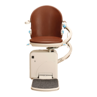
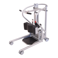
Figure 50
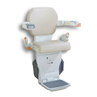
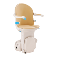
Figure 51
18 MINIVATOR SIMPLICITY
+
INSTALLATION MANUAL
Electrical connections / chassis covers
Electrical connections
Items required: Tools required:
• None • None
1 Make seat and footplate electrical connections
(Figure 50).
a Connect the key switch loom
(orange and green).
b Connect the toggle loom
(white, blue and brown).
c Connect the safety edge loom
(flat six way connection: 2 x brown,
2 x red and 2 x violet).
d Connect the six way footplate loom.
Powered footplate only
e Connect the powered footplate looms
(twin yellow and grey comms).
Power swivel only
f Connect the grey powered swivel loom.
g Connect the shielded swivel loom earth
ring terminal.
2 Test the function of the powered features,
including the toggle (see pages 24/25).
Fit the front chassis covers
Items required: Tools required:
• Top front chassis cover • Side cutters
• Bottom front chassis cover
1 Clip in the bottom front cover and fit the panel
fixing push studs.
2 Fit the top front cover and secure with the
supplied panel fixing push studs (Figure 51).