8 - Technical specifications
101
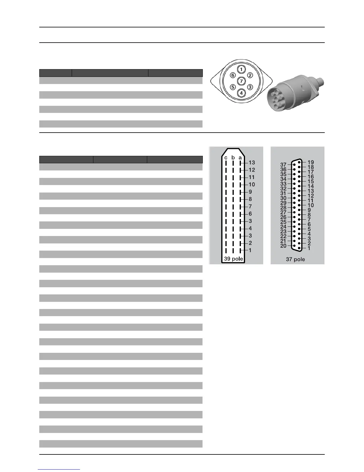
Electrical Connections
Rear Lights
The wiring is in accordance with ISO 1724.
Electrical Connections for Spraybox II and III
39- or 37-poled plug with cable.
Position Designation Wire colour
1 Left direction indicator Yellow
2Free Blue
3 Frame White
4 Right direction indicator Green
5 Right rear position lamp Brown
6Stop lamps Red
7 Left rear position lamp Black
39-pole 37-pole Spraybox II and III
1a 5 S1+
1b 6 S1-
1c 26 End nozzle L
2a 7 S2+
2b 8 S2-
2c 25 End nozzle R
3a 9 S3+
3b 10 S3-
3c 29 +12V sensor
4a 11 S4+
4b 12 34-
4c 4 PWM 1TX
5a 14 S5+
5b 15 S5-
5c 27 GND
6a 16 S6+
6b 17 S6-
6c 13 Optional 5 Reg. feedback
7a 18 S7+
7b 19 S7-
7c 33 Option 1 4-20mA
8a 37 S8+
8b 36 S8-
8c 32 Option 2 Frq
9a 35 S9+/Air angle 0-5V
9b 34 S9-/Fan speed 0-5V
9c not connected Option 3/Tank gauge
10a 21 On/off+
10b 22 On/off-
10c not connected PWM Output option
11a 23 Pressure+
11b 24 Pressure-
11c 28 Flow
12a 20 Foam blop 0-5V
12b 1 Option 4 Rx
12c 31 Speed
13a 3 FM L
13b 2 FM R
13c 30 Gnd sensor