3 - Description
19
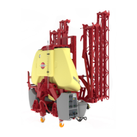
Clean Water Tank
The water in this tank is for hand washing, for cleaning of clogged
nozzles etc. Only fill this tank with clean water from the well.
The clean water tank is placed on the sprayer’s left side, right behind the
manifold valves.
Capacity: approximately 15 litres.
±
WARNING! Although the clean water tank is only filled with clean
water, this water must NOT be used for drinking.
Filters
A suction filter is fitted at the top of the tank. It is indicated with a red
hose tail.In-line pressure filters can be fitted at each boom section as an
option(J). However, it is standard equipment on this sprayer.
Nozzle filters are fitted at each nozzle.
All filters should always be in use and their function should be checked
regularly. Pay attention to the correct combination of filter and mesh
size. For more, see “Technical Specifications” in this book.
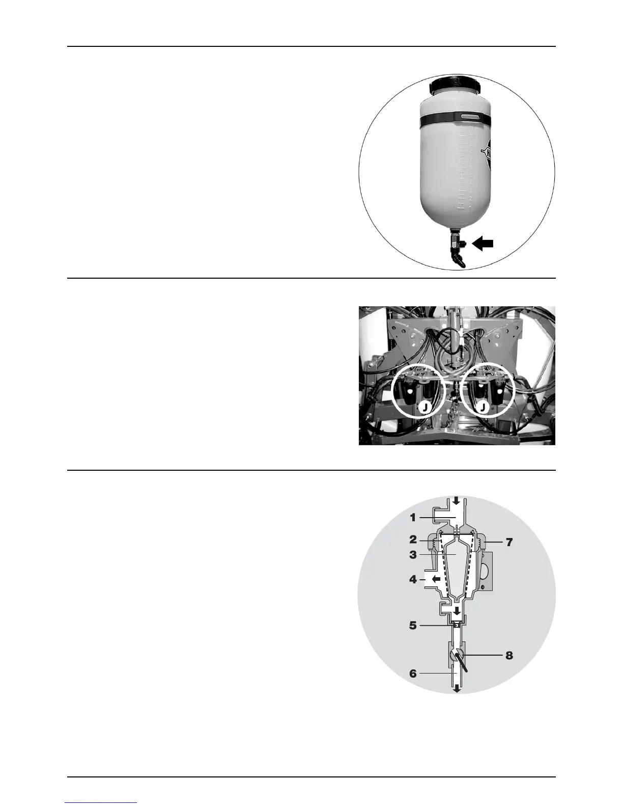
Self-Cleaning Filter
With the self-cleaning filter, the impurities that exist in the spray liquid
will be filtered out and returned to the tank via the return flow.
Function diagram:
1. From pump
2. Double filter screen
3. Guide cone
4. To operating unit
5. Exchangeable restrictor
6. Return to tank
7. Screw joint
8. Ball valve
Ball valve (8) should normally be open, but it may be closed in situations,
where return flow is to be avoided, e.g. flushing of spray lines without
diluting the spray liquid in the main tank.
μ
ATTENTION! If the ball valve is closed, the self-cleaning function is inoperative!