3 - Description
41
3 Calibration Basic calibration ,e.g. speed, boom, regulation constant, tank and track
3. 1 Speed calibration Sprayer, tractor, Alpha or radar speed input. Calibration of selected sensor
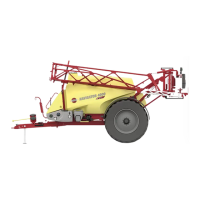
3. 1. 1 Sprayer speed Speed sensor mounted on trailed sprayer Connected to armature junction box
3. 1. 1. 1 Sprayer speed constant Shows and permits change to the constant, Pulses Per Unit (meter / feet)
3. 1. 1. 2 Sprayer speed practical Preferred method. Do in field with spray tank half full for most accurate result
3. 1. 1. 2. 1 Sprayer practical Measure up a distance more than 70 meters or 200 feet. Then drive distance
3. 1. 1. 2. 2 Sprayer practical Now key in the exact distance, measured by a measuring tape
3. 1. 1. 2. 3 Sprayer practical This is the new constant (pulses per meter or feet)
3. 1. 2 Speed from SmartCom or IsoBus Choose sensor connected to SmartCom or via CanBus
3. 1. 2. 1 Speed Sensor or Radar SmartCom pin input from sprayer wheel speed sensor or from tractor radar connector
3. 1. 2. 2 Speed via ISOBUS Speed via ISOBUS cable from GPS or Tractor ECU
3. 2 Flow calibration Flow sensor calibration. Theoretical (PPU), Nozzle Tank method PrimeFlow
3. 2. 1 PPU theory method Use the PPU value on Flowmeter housing
3. 2. 2 Nozzle method Practical flow calibration, by checking the actual nozzle output per minute
3. 2. 2. 1 Nozzle method measure the flow per minute from a number of nozzles. Press Enter.
3. 2. 2. 2 Nozzle method Key in the averaged actual flow value and press Enter
3. 2. 2. 3 Flow calibration This is the PPU constant from the volume previously just measured
3. 2. 2. 4 Nozzle method Open all sections
3. 2. 2. 5 Nozzle method Close end nozzles, Bi-jet nozzles
3. 2. 3 Tank method Practical flow calibration done by emptying over half the tank
3. 2. 3. 1 Tank method The sprayed amount is counted up when the sections are opened
3. 2. 3. 2 Tank method Press Enter. The shown volume is adjusted to match the actual volume
3. 2. 3. 3 Flow calibration This is the PPU constant from the volume previously just measured
3. 3 Boom setup Boom width, number of sections and number of nozzles for each section
3. 3. 1 Width The total spray boom width. Include end nozzles if fitted
3. 3. 2 Number of sections The number of spray boom sections. Keyin, then press Enter
3. 3. 3 Nozzles / sections To set up no. of nozzles per section. Screens for each section will appear
3. 3. 3. 01 Nozzles / sections Use arrow keys or numeric keys, then press Enter to set up section 1
3. 3. 3. 02 Nozzles / sections Use arrow keys or numeric keys, then press Enter to set up section 2
3. 3. 3. 03 Nozzles / sections Use arrow keys or numeric keys, then press Enter to set up section 3
3. 3. 3. 04 Nozzles / sections Use arrow keys or numeric keys, then press Enter to set up section 4
3. 3. 3. 05 Nozzles / sections Use arrow keys or numeric keys, then press Enter to set up section 5
3. 3. 3. 06 Nozzles / sections Use arrow keys or numeric keys, then press Enter to set up section 6
3. 3. 3. 07 Nozzles / sections Use arrow keys or numeric keys, then press Enter to set up section 7
3. 3. 3. 08 Nozzles / sections Use arrow keys or numeric keys, then press Enter to set up section 8
3. 3. 3. 09 Nozzles / sections Use arrow keys or numeric keys, then press Enter to set up section 9
3. 3. 3. 10 Nozzles / sections Use arrow keys or numeric keys, then press Enter to set up section 10
3. 3. 3. 11 Nozzles / sections Use arrow keys or numeric keys, then press Enter to set up section 11
3. 3. 3. 12 Nozzles / sections Use arrow keys or numeric keys, then press Enter to set up section 12
3. 3. 3. 13 Nozzles / sections Use arrow keys or numeric keys, then press Enter to set up section 13
3. 4 Regulation user setup Setup of pressure filter, nozzle, ASC default
3. 4. 1 Flow sensor restriction Flow to obtain 1 bar pressure drop over pressure filter and flow sensor
3. 4. 2 Simulated speed value Type in speed for priming at stand still and when both flow and pressure are defect
3. 4. 3 Nozzle size flow at 3 bar Nozzle output l/min
3. 4. 4 Dual line second nozzle 0075Pink = 0.3; 02Yellow = 0.8 04Red = 1.6; 08White = 3.2 l/min
3. 4. 5 Type of nozzle Select Regular or QuintaStream nozzle
3. 4. 5. 1 Regular nozzle Flat fan, Low drift, Minidrift
3. 4. 5. 2 QuintaStream QuintaStream fertiliser nozzle
3. 4. 6 ASC map headland gap ASC map headland gap display setup
3. 4. 6. 1 HARDI/AgLeader displays HC 8500, HC9500, Versa, Integra, HC 8600, HC 9600, InCommand
3. 4. 6. 2 3rd party ISO displays John Deere, TopCon, ME (including HC7500), Trimble and other
3. 4. 7 Limit for sim speed value Type in limit for simulated speed value
3. 4. 8 Reserved Reserved Reserved Reserved
Menu Number Menu Name Help Text in Display

 Loading...


