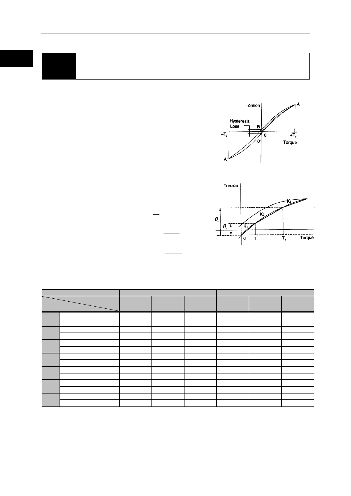
1-8 Torsional stiffness
1-9
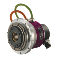
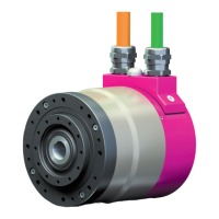
Overview of the RSF supermini series
1-8 Torsional stiffness
When a torque is applied to the output flange of the actuator with the motor locked, the resulting
torsional wind up is near proportional to the torque.
The upper right figure shows the torsional stiffness
characteristics of the output flange applying torque starting
from zero to plus side [+T
0] and minus side [–T0]. This
trajectory is called torque-torsion characteristics which
typically follows a loop 0→A→B→A’→B’→A as illustrated. The
torsional stiffness of the RSF supermini actuator is expressed
by the slope of the curve that is a spring rate (wind-up)
(unit:N・m/rad).
The torsional stiffness may be evaluated by dividing
torque-torsion characteristics curve into three major regions.
The spring rate of each region is expressed K
1, K2, and K3
respectively.
K
1: spring rate for torque region 0-T1
K
2: spring rate for torque region T1-T2
K
3: spring rate for torque region over T2
The wind-up for each region is expressed as follows:
wind-up for torque region 0-T
1:
wind-up for torque region T
1-T2:
wind-up for torque region over T
2:
The following table shows average values of T
1 through T3, K1 through K3, and θ1 through θ2 for
different gear ratios.
Gear ratio
Symbol
30 50 100 30 50 100
T
1
K
1
θ
1
T
2
K
2
θ
2
K
3
 Loading...